|
|
|
Introduction Drawing with a ComputerCAD is an acronym for Computer Aided Drafting or Computer Aided Design. The first definition is more applicable in this article but when even simple CAD programs are used to the fullest extent, the "design" aspect becomes the dominant factor in the process. CAD software is tool available to woodworkers that can be used in the normal coarse of building projects, jigs, and planning many activities that take place in the shop. Drawing with a computer is similar to drawing with a pencil except there are many more options available to the user for drawing precise vectors. Types of Software There are basically two types of software that can be used to draw images with a computer. The first is a painting program that will produce what is known as a "raster" type file format; an example of this type of software would be Windows Paintbrush. In these programs, when a line is drawn it is actually a series of pixels (squares) from one end to the other. For many reasons, paint software is not suitable for drawing and designing even simple objects. Paint software is analogous to a Digital Paintbrush. The other type of drawing software is one that produces a "vector" type file format. In these programs, when a line is drawn it is really a database object with several parameters assigned to it. In its most simple form, when the view is zoomed in, the line maintains its high resolution with no loss of detail. This is a very important distinction for printing, scaling, and editing purposes.
To somewhat confuse the issue, not all vector software is considered true CAD software. Illustration software uses a vector file format and may include functions for gradient fill colors, color separation controls, smart connecting symbols, and the ability to integrate raster images into the drawing. There are several downsides to this illustration software. Aside from the having only rudimentary vector editing tools it is "paper centric", the drawing is in relation to a virtual piece of paper and there are limits to the drawing size, drawing space, precision of drawn elements, and the zoom levels. In order to fit a design onto the paper centric file, it must involve some up-front scaling selected by the operator, this can become very cumbersome. Although one can at least use illustration software to produce measured drawings it is not truly suited for this type of work. Illustration software is analogous to a Digital Crayon. True CAD software is totally different from illustration software, it uses a vector file format but it is FAR more precise and contains many more tools and features that allow drawn objects to be modified in virtually any relevant way imaginable. CAD software worthy of the name does not use a "paper-centric" drawing interface either. With CAD software objects are drawn in true scale; if a cabinet is 76" high, it is drawn 76" high. There is still a place for scaling in CAD but it is done at the users command, not required in order to draw everything. When drawing with a CAD program, pre-drawn objects or externally referenced drawings can be easily used within a new drawing. This can reduce the amount of new content in a drawing and saves considerable time. There are varying levels of sophistication among CAD software programs, even the cheap ones sold today would have sufficient capabilities to be used to create very precise drawings. CAD software is analogous to an Extremely Sharp Digital Pencil. For the rest of this article the type of CAD software referred to will be the low-end / inexpensive type operated in simple 2D just like one would use a traditional drafting board. CAD Can / Can’tAlthough CAD software is a powerful tool, there are a few things that it cannot do. It will not draw objects for you, it will not determine joinery details, it will not automatically note interference's between parts, and it will not prevent you from drawing objects incorrectly. The main problem with CAD software is that it has such a steep learning curve. The main benefit of CAD software is that if used correctly, it produces drawings almost as a byproduct of the design process. Also, due to its ability to modify existing designs it is often quite easy to modify them into new designs, compare different variations of a design, and update changes to designs that are "in-process". Unfortunately, all of this is predicated upon the ability of the user to operate the software in a very time efficient manner. Fortunately, even the low end CAD software is capable enough to be used in woodworking. There are differences between the various CAD software programs but a description of them is outside the scope of this chapter. Woodworking and CADOnce a user gets past the learning curve, CAD can be a powerful woodworking tool; among other things, it can be used for: |
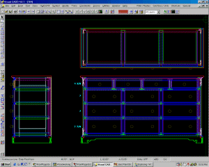
| Designing woodworking projects CAD can be used to design the overall size of a project, the types of joinery to be used as well as dimensions of any or all of the separate parts of the project. The easily editable nature of the file makes it very easy to make changes to the design as well as compare different design styles, sizes, and features before anything is built. The example shown is an orthogonal "stack-up" for the design of a triple dresser. |
 |
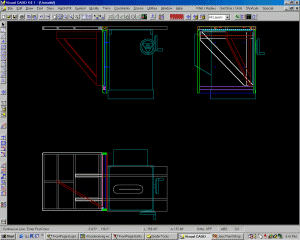
| Designing jigs and shop aids Many designs for jigs and fixtures might need to take into account several factors to in order to arrive at the optimal design. Because the constraints themselves can be drawn it makes the rest of the design much more controllable. If desired, 1:1 plots can also be made for templates or direct measurements in the shop. The example shown is a design for a folding outfeed table for a cabinet saw. Having the saw to draw upon greatly simplified the design since all the critical elements were right there to use. |
 |
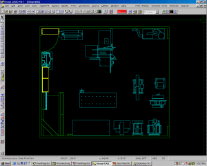
| Shop layout and planning Shop machine locations, work flow, or any other area-studies can be done "virtually" before any real shop items are moved. A good use of this could be to find the optimal position of the saw taking into consideration the need to rip 4x8 sheets and 10' long lumber. Designing the layout of dust collection, lighting and other aspects can also be done. |
 |
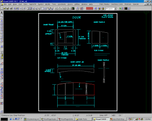
| Shop drawings Drawings specifically made to be used in the shop to build a project. How the drawings are laid out, what they contain, and how they convey the information is all under the control of the user. They can be made to fit on standard 8 1/2 x 11 sheets or larger plots can be made if large format printers are available. This example shows the drawing for a cabinet door. It includes the information for the door frame, door panels, as well as two templates used to create the curved aspects. |
 |
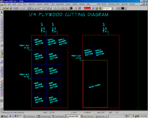
| Cutting diagrams Planning cuts in plywood sheets or other stock can be decided upon in advance. This should help reduce costly errors that can be made when breaking up large sheet goods as well as to help optimize the yield. I often use a drawing like this to plan the initial rough cuts. It allows me to visually lay out the parts and place the first critical cuts such that I ensure that I have adequately oversized parts for the final "sizing" cuts made later. |
 |