Woodworking with CAD

Woodworking With CAD Index

From the Requirements...
In a previous "Concept" article I laid out the scenario of developing requirements for the example bookcase. For review, the known requirements are:

1. Able to store 72 linear inches worth of books.
2. Storage for several CD jewel cases on edge in a drawer.
3. Less than 38" overall width to avoid covering a window on a wall where it could be placed.
4. Doors.
5. Adjustable shelves.
6. Not too tall.

Lets assume that we want to find out if it is possible to build such a project and install it in its intended location. We will use CAD to help us figure that out.

Feasibility Study
This is a general term for finding out some dimensional requirements / capacities. If all the issues have been nailed down before hand then this step does not need to be done. If they are not resolved however, it could be because you want to use CAD to help you figure out some sizes given some other known constraints. The intent of this stage is NOT to settle upon every detail of a design.

Step By Step
The steps below are a "walkthrough" for an feasibility study. There is no one process that must be followed. The process below is only intended as a starting point. Once you gain familiarity with how to bring a project to completion, you may find some other process works best for you.

Step 1
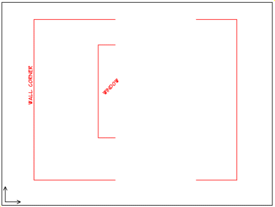
Basically what one would like to do first is to draw the constraints that are "draw-able". In our example this would be a sample wall with a 96" high ceiling and a window 38" from a corner (remember, the cabinet cannot exceed the 38" dimension to keep from intruding on a window and it can't be "too tall"). Notice that we had no maximum depth requirement. We will however establish a "back" plane to use as a reference for the depth. All this information will be referred to as the "Constraint" from now on, it should be drawn on a layer of its own.
Constraint
The major task in this step is:

1. Draw the Constraint layer. The illustration at this point doesn't really look like anything at all, certainly not a cabinet; right now it doesn't need to; it's just a base-line to start from.

This Constraint layer is important for the reasons given above. However, it has another important purpose for a beginner as well, that is it gets the new user out of the "blank-screen lock-up" mode that is an impediment to getting anything done. Basically, it gives you a definite place to start from.
Step2
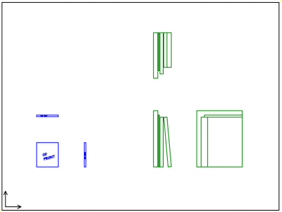
The Constraint isn't visible in this view. That is because I've panned over to an open space in the drawing to draw these new shapes. With true CAD software you are free to draw wherever you want, it is very easy to move drawn objects around later.

It is important that the Contents have a front, right side, and top view, at least for now. Because they are such basic shapes, you might want to label them so there is no mix-up.
Contents
The major task in this step is:

1. Draw the Contents, (CD jewel case, books) each on their own layers. This will seem very obvious to an experienced CAD user but I want to point out that at no time have I been concerned with the co-ordinates or where the drawn elements are in the virtual CAD "world". All I really care about is making sure the drawn elements are the actual dimensions needed and making sure they relate to each other orthogonaly (ie: the CD case front-top-side views are lined up).

Step 3
You the woodworker will now begin to bring a host of assumptions into play here. For example, you KNOW that you will NOT be making shelves out of 3" thick solid stock, that would be absurd. You will be using 3/4" (or thereabouts) thick material. I'm mentioning this here to point out that you as the designer and builder will be placing your own HUGE set of requirements onto the project, some of these are known now, other may be discovered later.

Using some of our own requirements it is possible to draw a rough Framework that will hold the Contents. Because our size requirements are somewhat loose, the Framework will not push the envelope too hard, we can do that later if need be.

Framework
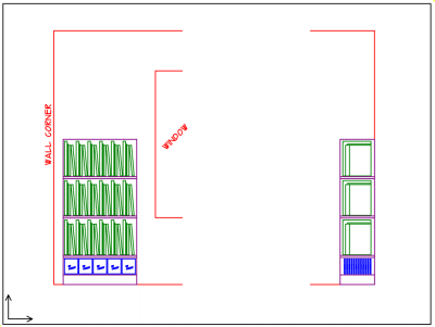
On it's own separate layer called Framework, I'll draw a very simple open shelf and place the multiple copies of Contents in it. We are essentially designing the project "inside - out" using this technique. One familiar with CAD could do all the drawings shown thus far this in less than 10 minutes. Note that this Framework may not be anything that that actually ends up getting built, it is really just a visual placeholder to orient copies of the Contents so we can do some size analysis work.

The major task in this step is:

1. Draw a simple shelf Framework
2. Copy the Contents and place them within the Framework.

At this stage you should begin to see how I've used the minimal information of the Constraint layer to place the Contents into a simple Framework. It should now be apparent that there is going to be a front, and right side view involved; we could have also done a top view. Notice that I've made sure that I've maintained alignment with the front and right side views of the Contents and the Framework.

By stretching and manipulating the existing drawing it should be pretty obvious at this point whether or not we are going to have trouble getting all of the stuff into the space allowed. If we were having trouble, we would need to start paying very close attention to the details and exploring more layout options. As it is though this project is proceeding along routinely without any major size concerns.

Who's Zooming Who?
It is at this point our story comes to a milestone in the development process. From the design work carried out thus far, it should be evident that this basic design is going to satisfy our original requirements pretty easily. The milestone is the end of the basic design (or first approximation) and the beginning of the Style phase. In this next phase we will consider with CAD how we want the outside of the cabinet to look. In order to do this we want to make sure we don't violate any our original requirements though. In effect, the new Framework with the installed Contents will become a second Constraint.

It would be wise at this point to double check the requirements and all the drawn elements. Any mistake in this area is likely to have a large negative impact on the project! We want to use CAD to catch problems before we start building in the shop.


Back to the Woodworking With CAD Index