|
|
|
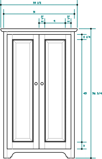
| The Fork It is at this point I believe the CAD operations come to a fork in the road (so to speak). By this point we should have a drawing of the basic design with a few details but these are not really enough to enable the building of the project unless you like to "wing it" from here on. I'm not making light of this because that is what a lot of people do. If you are the sort who doesn't like to plan ahead and know the dimensions of things well before they are made, 'winging it" is exactly what you would do here (and you need not read any further). If on the other hand you like to have things figured out a little before you build, the next operation depends on how much up-front work you want to do. I'll present two approaches and explain one of them in detail. |
|
| The first approach is to simply take the existing drawing,
probably a front and side view only, and slap a few dimensions on it then head on out to
the shop and crank it out. In magazine articles related to woodworking and CAD, this basic
level of information is what you see presented. It is interesting to note that this is NOT
what you see presented in magazine project articles though. They usually break up the
drawings into several pages with exploded 3D views, full dimensions for all the parts, and
some detailed views when required. The other approach is to basically draw all the parts and assemblies similar to what you might see in a woodworking magazine project article. You have to be aware that magazines use a variety of software to create their content and their presentation is not always what is required to build a project. For example, you can draw a 3D exploded and dimensioned view of a drawer (which is a nice drawing) but you can also present the same information in three 2D dimensioned views (not as pretty but useable). Stackup |
 |
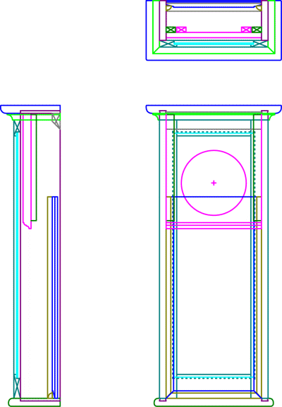
 A simple clock case "Stackup" |
This will ultimately yield a drawing that looks similar to a
"wire-frame" (but it isn't really). The Stackup can resemble a confused jumble
of lines when all the layers are displayed. The user needs to be proficient in turning the
layers on and off in order to reduce the clutter. The user also needs to have some
proficiency to keep the front, side, and top views of the part in sync as well during
various editing processes. Once you become a reasonably proficient CAD operator, it
isn't too difficult to do all this even in 2D software though. Presented here is a simple wall clock case that has been drawn as a Stackup. Note every part has been represented in each of the three views as well as some of the joinery involved. It would be possible to copy the individual layers in order to create a dimensioned drawing of each part represented here. This is the stage where the power of a solid modeling CAD system
would come into play (which we are not using). One reason for this is because making
sure the three 2D views remain in sync is a completely manual process and there is an
opportunity for error. |
| Part by Part To draw the Stackup, the best place to begin is from one of the earlier Concept drawings. You can draw on top of it or manipulate existing elements as you wish. In our sample cabinet I would start by drawing the vertical sides, doors & panels, top, horizontal case pieces, moulding, and anything else evident from the exterior. Now all these pieces will be (again) drawn on their own named layer and each in a front, side, and top view; even if they become obscured by another part. For example, the door frame(s) will be drawn in a front, left, and side view on a layer named Door_Frame. It is important to understand that we are not really making a drawing here (yet), we are making an engineering data base. After all the easy stuff has been taken care of it is time to take care of the rest, the interior drawers and shelves for instance. Usually when it comes to these elements a little more thought needs to be applied. This isn't because of CAD, it is the usual sort of work that needs to take place in any design. For example at this stage you would be dealing with drawer glide clearances, exact drawer and shelf stock thicknesses, clearances for CD cases and books, and so on. Assume for a moment that all the interior and exterior part have been drawn in all three views. You still may not be ready for the next step. If you remember back in the Style article I said joinery design does NOT take place there; that is because it should take place at THIS stage. Undoubtedly, at this time you will need to figure out if two parts should mate with a single tenon or a double, a dovetail or a lap joint, a rabbet or a pocket hole and so on. The key here is to make all these decisions on the Stackup, you should not leave this stage before all these details are worked (thus drawn) out. This stage is one big continual edit. I trim, stretch, copy, move, mirror, and otherwise draw things in order to DESIGN them to fit together. During this process I may adjust the locations of the Contents in order to suit some physical design need. Also it may not be intuitively obvious but at this level I have been applying quite a bit of personal style in the drawing. For example, the door was made using a separate frame and panel, not a separate rail, stile, and panel. Remember, the Style layer is only a guide, After I’ve drawn all of the stackup layers I may find that the project is slightly different that what appears on the Style layer. It should however still meet all the requirements. At this stage I don’t need the Framework layer because its function is now being served by actual project parts. If I don’t alter the design I no longer have a need for the Constraint layer but may keep it anyway. I do want to keep the Content layer. I may or may not decide to edit the Style layer to match the new reality. |
| Close Inspection After all the major tweaking and editing has taken place I double check the stackup. This is a manual process, I do it by turning all the layers off then turning layers on one by one to ensure that the views are completely drawn and that the parts line up correctly. From this information, we will be able to do take-offs and create the shop drawings we need to build the project. |