|
|
|
| What is a CNC
Router? In the past CNC tools were confined primarily to industrial use. These were usually large and enormously expensive machines. Although these machines still exist, so do also a new breed of smaller, less expensive machines that are much closer to being economically affordable. A CNC controlled router is basically a robot guiding a router or spindle. These are not the only tools these machines can wield, they can also use drills, knives, pens and other more specialized tooling. For sake of simplicity, this article focuses on relatively basic "inexpensive" CNC routers used for woodworking. |
 |
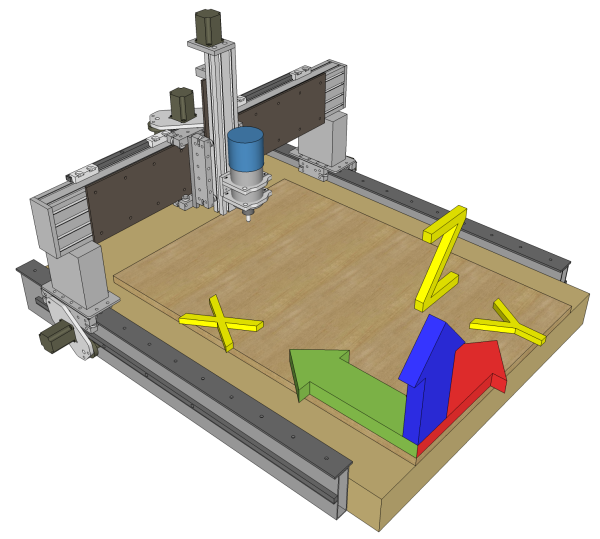
| A basic CNC router will enable the cutter to be placed at any point guided by 3 axes of motion simultaneously. That means it can move the cutter left-right, from-to, or up-down all at the same time. That makes it possible to cut curved lines as well as straight and even vary the height of the cutter while doing so. This makes it possible to follow any 2 dimensional profile as well as in 3d space. It is possible to do 3d carving so long as there are no undercuts. Sometimes a 3 axis system is referred to as a 2.5d capable system due to limitations such as this. Depending on the project, it may be possible to flip the work piece and carve from an opposite or adjacent side to achieve a more 3d effect. |
| Game Changer You don't have to have much woodworking experience to realize that a router is one of the most versatile tools in the shop. A CNC router can take that very same tool and under programmatic control use it to cut and shape wood in ways that you would never dream of doing by hand. A CNC router is a "game-changing" tool, a very big leap forward in capability. It should therefore come as no surprise that there is a new learning curve to climb in order to use one. If you are using CAD drawn plans in your shop, a CNC router is the next natural progression of the use of that tool. If you are not using CAD, you will be in for a steeper learning curve. |
 |
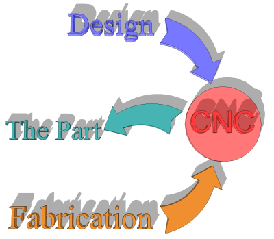
| CNC Work Systems A CNC router is actually a part of two dependant systems which must be employed in order to produce anything. There is a Design System and a Fabrication System. The Design System is comprised of the Concept, CAD/CAM (and files), and the CNC machine. The Fabrication System is comprised of Work holding, and the CNC machine. |
|
 |
The Design System starts
with some kind of Concept of what you want to achieve. The CAD/CAM phase involves drawing and/or use of preexisting files in order to bring that Concept to reality. The output of this phase are the tool path files the machine will use. The CNC machine itself is involved because it dictates what can and cannot be done in particular dimensions, this has an effect on how the tool paths are made (design). How fast you can move the cutter is also machine dependant and impacts how you design the tool paths. |
| The Fabrication System starts with some piece of stock that must be affixed to the machine. This is called work holding or fixturing. The task and material may require some special way of affixing the stock or even a dynamic clamp that is part of the CNC machine itself. Fixturing is a constant issue when it comes to using the machine. If you process even a few different materials or stock configurations you will need multiple methods of work holding techniques. The CNC machine is (naturally) a component of the Fabrication System as well. The machine must be setup and reset with known references and often tool changes must be accomplished during fabrication. | |
| Using a CNC
Router A side effect of using a CNC tool is that it will tend to skew the project more towards a design centric endeavor. That is, you have to design (draw) the parts in some manner in order to create whatever designs etc that are going to be made. The more a CNC tool is incorporated into the whole process, the more up-front design work that must be done. Once you have even a fair understanding of how your CAD and CAM software works, you will be able to incorporate a CNC into your work without a lot of effort, it isn't that hard. It's actually far more difficult deciding WHAT to do - that is literally because the sky is the limit on what can be done. Using a tool such as this will often alter the entire workflow from what might have been done prior. For instance, you can cut, carve, drill, and profile a part all on the CNC machine in one work cycle as opposed to using the several discrete tools that it would have taken with more manual methods. Another side effect of using a CNC tool is that you are physically removed from the actual work. That may sound pretty obvious but there's an important aspect to mention and that is safety. For those operations taking place on the CNC, you are quite a bit out of harms way. With manual tools you are pushing stock past high speed cutters, holding material that could be grabbed out of your control, etc; with CNC, you are not. |
| Workflow Using a CNC router involves a new workflow in the shop. Presented here is a typical workflow diagram for a specific part. CNC work flow may be simpler or more complex than this, it just depends upon what the project calls for and your methods. From a Concept, a typical workflow may start out in CAD. The output of this might be a vector DXF file that is imported into the CAM software. This file may be "tool path ready" or require additional vector work within the CAM software. If needed, the user might also import bitmaps, vector files from other sources, or 3d models with the intent of creating all the tool paths needed for a particular project part; all within the CAM software. The CAM software will also allow you to simulate the tool paths you create. These will show how the finished part will look in general. You can also display these previews to a client for final approval should you need to do so. Once all of the tool paths are created output files are produced. These are not the same as the CAM file itself. These are files formatted to your specific Machine Controller (MC). Generally these are text files containing standardized G-codes that the Machine Controller can understand. |
| The next step requires installing some
raw or preprocessed material onto the CNC machine( Fix on the diagram). This might
be as simple as screwing the material down or involve the design and use of special
fixturing devices to hold the material in some particular orientation. At first
glance it might seem that fixturing is a rather small portion of the task not really worth
mentioning. In actuality, it's fundamentally critical to the entire process. The Machine Controller is represented as the software front end for the electronics that actually drives the CNC machine. This software is configured to the exact parameters needed to control your specific machine. Sometimes you may see the Machine Controller referred to as a "Post Processor", that is not correct, the "Post Processor" is actually a file pattern generator the CAM software uses to output a file compatible with your CNC machine. After fixturing, the MC is used independent of the CAM output files to establish references so the machine knows where the part is in relation to "zero" in all X Y Z axes. Once this is done with an appropriate tool, the tool path(s) are loaded in and the Machine Controller is able to run that profile on the CNC. It might be necessary to change tools one or more times or establish different references during the work cycle, it depends upon the project and tool paths. The diagram presented above is generic in nature. Your specific machine and software will dictate some parts of the workflow as will also the project and your methods. |
| Summary A CNC router isn't magic, it just appears that you can do "magic" with it; it's just another tool albeit an extremely capable one. Using a CNC router in a woodworking shop means "changing your game", how much depends entirely upon how you want to use the tool. The tool itself will not dictate any change except that designs must be done before using the tool. |