|
|
|
The 32mm System and the Festool Hole Guide
 |
 |
 |
 |
 |
 |
 |
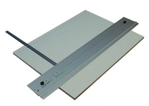
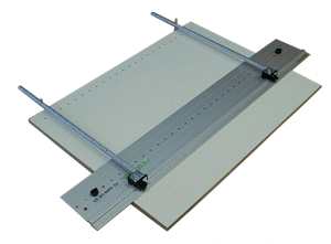
| The Festool Hole Guide
System can be used in basically two modes, free-form and as a 32mm system hole guide. In
free-form operations I think the most common use would be to create a series of shelf pin
holes in cabinets. For simple shelves you are not rigidly constrained to any standard, you
can drill however many holes you wish, wherever you wish across the width. Using the
system in this manner is pretty straightforward, the guide is placed as desired and the
holes are drilled. If you want to use the Festool Hole Guide in what is known as the 32mm
system, there is a bit more involved, mainly in guide location. Metrics |
|
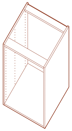 |
Overview of 32 There are books dedicated to the 32mm design philosophy, this is only a very brief overview. The name of the 32mm System originates from the center to center spacing of the holes in the drill pattern. These holes control the locations of door hinges, drawer glides, other hardware, and the locations of the parts that make up the cabinet itself. The system allows a builder to accurately bore the required holes to ensure all the cabinet parts line up correctly. Another source for 32mm information worth looking at comes from hardware suppliers like Blum and Hettich. A typical 32mm system cabinet box would be made of five main part. There are variations in construction, THE 32mm system may not be the same as YOUR implementation of the 32mm system. The aspect that remains fairly constant though are the system holes on the cabinet sides. The image shown here is of a base cabinet, these might sometimes be made with a solid top (such as in a wall cabinet) or as shown here with two narrow stretchers. FYI: There is an American variation on the 32mm system that uses 1�" as the base increment, (1�" = 31.75mm). I am going to stick to 32mm herein because that is the spacing of the Festool Hole Guide. |
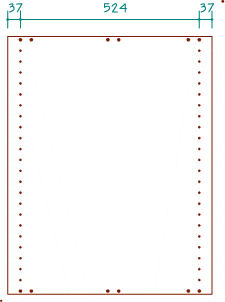
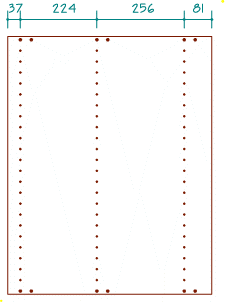
| Holes There are two basic kinds of holes to be aware of in the 32mm system, "construction" and "system" holes; this article deals mainly with system holes. The system holes are vertical sets of holes that accept the standard 32mm hardware such as drawer glides, hinges, shelf pins, and quite a bit of other hardware. Construction holes are bored to accept the dowels used to assemble the box (dowel joints are not a requirement of the 32mm system). The construction holes are typically 8mm in diameter, the system holes are usually 5mm, the construction and system hole patterns are not necessarily directly tied together either. There is more than one strategy for laying out the holes in the side panels. The main (as far as I know) types of layouts are known as Balanced, and Unbalanced, illustrated below are examples of these. Note that the Balanced panel could be rotated 180 degrees and still be in the same configuration meaning the front could be either edge. This would not be true of the Unbalanced panel. |
|
| Balanced | Unbalanced | |
|
|
|
| Drilling the holes for
this panel is actually quite simple. A 37mm setback is set using the Hole Guide
positioning arms and the holes are drilled on one side, the panel is rotated 180 degrees
and the other side is drilled - piece of cake. A Balanced panel design makes a lot of sense for a commercial operation. For smaller shops, it may not be the best idea for anything other than simple shelf pin holes because of the accuracy issues. |
An Unbalanced panel requires a little more thought. You can imagine that the first series of holes in this panel would be located and drilled the same as the Balanced panel. The second series of holes (on the opposing edge) however is a different distance from the edge, a 37mm setback will not work here, 81mm is required; or is it? What is actually required is for the middle set of holes to be 224mm from the first set and another set of holes 256mm from the middle ones. The 81mm is actually a "float" dimension (not critical). |
| Layout Across the
Panel From the examples shown above, it probably isn't too hard to figure out that the Balanced panel is very easy to make particularly if all you need are shelf pin holes. There is a critical issue related to a Balanced panel if the holes are located from a second reference. The problem is that variations in panel width have a direct impact on the distance between holes. In order to use 32mm system hardware such as drawer glides, the distance between holes must be in 32mm increments. There are a number of ways to achieve this using the Festool Hole Guide, three are presented below: |
| 1. | Use the second edge reference. This is basically like using the Balanced panel method except that to drill the second set of holes (from the opposing side of the panels 37mm holes) the positioning arms would need to be reset (to 81mm in our example above). If very many panels were required, it would probably be best to batch this process to keep from having to reset the positioning arms. The problem (again) is that to work with all the 32mm hardware, the panel width is critical. Another problem is that if a third set of holes are required on a wide panel. The positioning arms of the Hole Guide only go so far (~110mm), the middle section of the panel cannot be reached using them. |
 |
| This method would also require one to rotate either the panel or the jig from the first set of holes. This method may use different holes in the Hole Guide to drill opposing sets of holes in the panel; this is only an annoyance but it is also an opportunity for error. | ||
| 2. | Manual layout from first reference
edge. This basically entails layout without using the positioning arms; this would be done for any holes greater than ~110mm from the edge. As it turns out, the Festool system puts a hole 25mm away from the metal working edge of the guide. If for example a set of holes were needed 261mm from the edge (37 + 224), the guide could be set with its edge 286mm (261 + 25) away from the reference; this will put the holes right at 261mm. While this method involves some manual measurement it has the benefit of using a single reference edge to position the holes; it also doesn't require the jig or panel to be rotated so there is less chance of mix-up about which holes need to be drilled. |
 |
| FYI: To see how the addition of a second reference impacts the accuracy of the system, consider first that any cheap measurement tape is probably only accurate to +/- 1mm after 400mm or so; now add a potential of 0.5mm for other errors and our panel may be narrow or wide by 1.5mm. If the second reference method is used, the distance between holes may no longer be in the critical 32mm increments. | ||
| 3. | Jigs. There are numerous ways one could jig up the Hole Guide to place it in the proper position. One way would be to make longer replacement arms for the positioner. This could allow it to be used with a single reference and the jig would still be portable as well. One might also consider a positioning system that would only allow it to be moved to whole base units of the 32mm system; i.e.: 37mm, 69mm, 101mm, etc.. Another way to jig up the system would be to omit the positioning arms and move their function to a stop system in a table or fence of some sort. This might be a good solution if more production speed were required, it might not be too portable though. |
 Note, the jig pictured is a simulation |
| Layout
Up the Panel The discussion thus far has dealt mainly with locating system holes across the width of a panel, there is another critical issue in locating the system holes across the height of the panel. Using the Festool Hole Guide one can very accurately place a series of holes spaced 32mm apart. The system is supplied with a stop that fits underneath the guide and with this stop one can begin the holes either 32mm or 16mm from the edge as desired. However, in case work the starting system hole position is directly related to the thickness of the case material. |
|
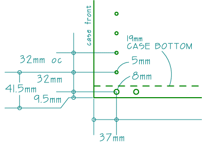
| In simple scenario, a system hole is
needed about 32mm from the center of the bottom of the case, This is how the
thickness of material comes into play. In order to get the critical 9.5mm (for 19mm
or 3/4" thick stock) pattern offset, I (currently) use a custom spacer block. Some makers use 10mm for the offset or 8mm if a 5/8" bottom panel is used. Basically though a drawer glide needs to have it's first locating hole at some distance other than the 32mm or 16mm induced by the Festool stops. FYI, the ~41.5mm dimension shown here is not a standard even with 19mm thick stock, Blum for example places this hole at 39mm. |
 |
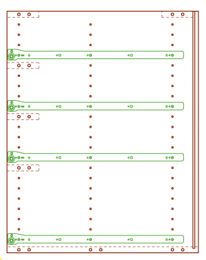 |
The image at left is an illustration
of how all this 32mm stuff comes together in a panel. This is a side view of the a
panel for a base cabinet with four drawers with its drawer glides shown
installed. Note that some of the holes in the 32mm pattern are system holes, others
are construction holes to allow the doweled cabinet rails and bottom to attach to the
sides. The horizontal case parts are represented by dashed lines in this drawing. The
unused holes seen on this panel aren't required, they do help to see the pattern though. This article is only a brief overview of how the Festool Hole Guide can be used with the 32mm system. |
 |
 |
 |
 |
 |
 |
 |