|
|
|
Jointech Clincher Rip Fence
System
for the Hammer B3 / K3
|
Preface Prototype |
|
 |
The ripfence used on the prototype is a fairly simple torsion box that is attached to the Cincher with two 1/4" bolts. The bottom has several small felt discs applied to provide a sawdust relief and to keep the fence off of the table surface so it would slide easier. It is very important that the fence be straight with flat faces 90 degrees to each other. |
| The system I came up with incorporates a sliding bridge to mount the Clincher to. The bridge is locked down to the extension table using two bolts with large wing nuts mounted in the bridge; the heads of these bolts slide along in a T-track imbedded into the extension table. The bridge needs to slide in order to get a range of motion greater than that of the Clincher itself; the Jointech and Small Incra systems do the same thing. | |
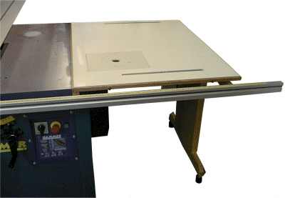
| Extension Table Since I prevented myself from using the existing rails to mount the new fence, I had to come up with an alternative. The solution was to build a new right extension table. Because of the problems brought about by the stock Hammer extension table, I would have eventually built a replacement anyway so designing it to accommodate another alignment system for the Clincher was not really a big issue. The replacement table is a very simple Melamine table with a supporting grid underneath it and supported by separate legs at the far right side. This particular table is not ideal but it serves my purposes at the moment. I also included a router table insert while I was at it. |
 |
 |
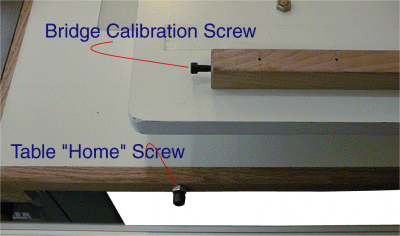
Fence System To provide the required calibrated "home" position for the bridge, there are two blocks on the underside that have 10-32 screws in their ends that will contact heads of larger screws imbedded into the side of the extension table. Because of the length of the bridge and the fine pitch of the screws, it is possible to align the home positions very precisely. Together the positioning of the Clincher onto the bridge and the bridge on the table creates an alignment system that it uses very common components to achieve a very accurate and repeatable alignment. |
| Just because the bridge can be aligned precisely, doesn’t
mean the Clincher and its attached rip fence are. To make sure that I could remove
and re-install the Clincher itself I used four undersize screws to attach it to the
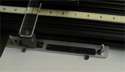
bridge, this allows for a little free-play before the Clincher base is bolted down. To ensure that the base always goes in the exact same spot on the bridge I used a three-screw head pattern on the bridge; when the base is pushed up against these screw heads, it can only be in one position relative to the bridge. Two of the screw heads are visible in this view and the third is to the right under the Clincher extrusion out of view. |
 |
| Evaluation After using the Clincher for a short period all seems well until the fence is needed at a position other than what can be obtained in its left "home" position or it needs to be removed for a big crosscut. If there were no limitations to the right of the table in my shop this would be less of a problem. Although the system is easily removed and re-installed, the weight is a little prohibitive and it is more prone to going out of alignment because this assembly is less robust (only in terms of alignment) than a typical rip fence. On the plus side it is beneficial to be able to adjust the fence in small increments even when used on a saw. Even though the system cannot deliver on its full potential rip capacity in MY shop, it still does have some merit. Judging from the wear patterns on my previous rip fence, most rip cuts are in the 0"-12" region anyway and this system can easily satisfy that capacity. The Clincher system described herein is not limited to use on an odd-ball European machine, the track-mounted system could be used on any other saw with an extension table as well. Further Development
|