|
|
|
New Rip Fence for the Hammer B3 / K3
 |
 |
 |
 |
 |
 |
 |
Return to the Hammer B3 Index Page
One of the constraints I had to account for in the selection was the fact that the right extension table of my machine normally abuts a wall. This effectively eliminates either of the two precision positioning systems from consideration since they require a significant amount of free space to the right of the table to be used to full capacity. Installation Due to the lower position of the T-square section on the table the stock fence clamping nuts would hit the table when turned. To eliminate this I replaced the stock knobs with 5/16" lever knobs. A 180 degree twist is all it takes to tighten or loosen the fence. Instead of bolting the rip fence rail directly to the main iron table as is commonly done I used a �" thick, 2 �" wide angle iron section to mount the fence. The angle iron is bolted into the same holes as the previous Hammer fence rails, the new fence rail was them bolted to the angle iron via four threaded holes I had put into the bottom of the rail. The angle iron section made the installation a little easier than bolting the rail directly to the machine. It should be pointed out that none of the modifications described herein require any change to the Hammer that could not be un-done. Also, none of the modifications to the new rip fence rendered it unusable for a subsequent installation on another machine. The removal of 1/8" of material from the bottom of the T-square head is not really noticeable and will not hinder its use on another machine. Extension Table Numbers With the fence in the high position it can be moved to within 7/8" of the blade. With the fence in the low position it can be moved all the way to the blade. Using the fence-low position to make up for the short-fall was acceptable to me; otherwise I would have used some form of spacer to make up the difference. With the rail installed on the machine I measured it at 0.8955" below the plane of the table. This provides for a small amount of clearance between the head and the sliding table without having to modify the fence to head attachment in any way. With the fence installed at this level below the table, the fence can be set onto the table or raised a little above to create a saw-dust relief. Differences Pro:
Con:
Conclusion Details: |
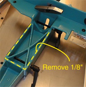 |
In order to install the fence low enough to fit onto the Hammer it became necessary to remove some material from the bottom of the T-square head. As indicated, I took off 1/8" in the areas shown. Removing the material was easy, the T-square head is made of aluminum. |
| There are a few ways that the new fence could have been installed. I attached a piece of angle iron to the cast iron table, this allowed me to work out any squaring issues prior to actually installing the fence rail. It is also an easier platform to deal with on what is essentially is an experimental installation. | 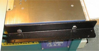 |
| The exact length of the
angle is not critical but it should be at least as long as the iron table is wide, I used
this size because this is what I found laying around. The angle could be as long as
the rail or table if desired. The angle I used is 2 1/2" wide, 1/4" thick steel, this makes the angle very strong, I would not recommend using anything smaller (in any dimension) than what I have shown here. I used the two bolts with over-size heads that came with the fence to install the angle. Flat-head Allen bolts could also be used and their holes in the angle could be counter sunk with an appropriate taper. |
|
 |
| To install the angle iron square to
the table I used the existing Hammer rail bolt holes. These holes are counter bored with a
flat face that is 90 degrees to the plane of the cast iron table. All that needed to be
done was to place a couple of flat washers in between the angle iron and the saw table.
This keeps the angle iron from abutting the cast iron table which would induce an angle.
This particular fence system will tolerate an installation bias angle of a few degrees but
it is always best to start out as square as possible. As stated, this is an experimental installation, to allow for calculation errors I intentionally installed the angle iron a little low. The reason for this was that it is easier to shim something up than completely re-install or re-engineer the parts to lower the assembly. To that end there are four flat washers between the fence rail and the angle iron. The fence rail itself is attached to the angle using bolts that thread directly into the bottom of the fence rail. The measurement of the rip fence rail below the table is critical; the measurement given (0.8955") is a direct reading from my calipers. There are some other ways to install the fence onto the machine. However, I believe the way I have presented the installation is easier.
|
 |
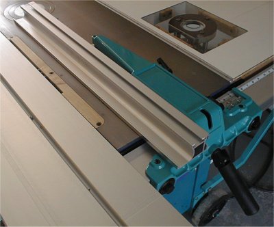
It is pretty clear that the T-square head is quite close to the sliding table wagon, there is a little over 1/16" of clearance. On sliders that are fully extended on the infeed side this could be an issue. It is possible to lower the fence further but any lower and one begins to intrude upon the allowance for a fence dust relief gap. |
| By relocating the fence
attachment bolt holes (up) the fence rail could be installed lower than shown.
However due to the geometry of the wagon the fence would not come appreciably closer than
shown here. At this time I am not using any device to limit the left-ward travel of the rip fence; meaning it is possible for me to move the fence closer to the wagon and bang it up. If I discover this to be a worthwhile feature I'll add something to the interior of the rip fence rail to accomplish this. |
|
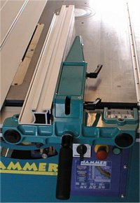
| This view shows the installation with the fence in the high position. I replaced the original T-knobs with lever knobs because the T-knobs come close to or hit the saw table when turned. Because I just wanted to, I re-painted the T-square head to more closely match the color of the Hammer. The little brown square seen on one of the lever knobs is a piece of cork to prevent any chipping of the paint when loosened. Before you ask, I have no idea why there is a slot in the T-square head.
|
 |
 |
To get all the way to the blade the
fence is placed in the "low" position shown here. Placing the fence in the
low position to enable it to reach the 0" - <7/8" region near the blade is an
acceptable trade-off to me. If it were not (or becomes an issue in the future) I
could easily come up with a 7/8" thick spacer to go between the fence and T-square
head. It may not be obvious but if the slider is moved into a position even with the iron table the rip fence can be made to go all the way to the blade with it in the fence-high configuration. |
| To the right can be seen the new right table extension with a router insert included in it. One reason for using this particular fence is because the aluminum fence section can be replaced with purpose built fences that can be used with a router table. | |
Return to the Hammer B3 Index Page
 |
 |
 |
 |
 |
 |
 |