|
|
|
 |
 |
 |
 |
 |
 |
 |
Presented below are a series of jigs and modifications I've employed with the Legacy Ornamental Mill. Most of these require very little effort and cost and I think they improve upon the base machine a noticeable amount. |
| This modification is very simple, low cost and improves the
Legacy quite a bit. I replaced the dead center in the tailstock with a live center.
The tail stock accepts a standard #2 Morse taper. This particular one was obtained from
Grizzly for a few dollars, any live center designed for a wood lathe should work well in
this application. The dead center has a tendency to become a little loose in use, the longer it is use the looser it gets. This results in a tendency to want to tighten it up which in turn can lead to a split piece of stock if one is a little too zealous (DAMHIKT). Because the live center has a center with a flat flange (excluding the cup) this provides a natural stop. With a live center there is no reason for the stock to become loose with use. |
 |
 |
This modification substitutes the Allen bolts used to fix the
bed at a specific angle with a cam clamp. On the Legacy there are six of these bolts to
loosen and tighten whenever the elevation or angle of the bed is altered. Three of these
are on the opposite side of the machine and depending on where the machine is located is
can be quite a nuisance to get to these when required. This particular cam was bought from Lee Valley and it fits a 1/4-20 bolt. This isn't the best cam for the job because it is critical what the overall length of the bolt is. Pictured in this view is a loose clamp that presents a better side view. While the Allen bolt design of the original system works it isn't very convenient and should be much better than it is, this cam clamp is an improvement which could be made even better. |
There are occasions when it is desirable to remove stock from the
Legacy for some other operation and then re-mount it into the machine. Sometimes the stock
securing "dog" interferes with whatever "off- Legacy" operation this
is. An example of this would be if one wanted to mount the stock into a traditional lathe. |
|
|
|
| The factory has an option for equipping the Legacy with a dust collection system. This system is comprised of a curtain either side of the carriage and an inverted tent device hooked to a 4" DC fitting; all this for about $250. That is pretty high for a few bucks of plastic and Velcro but a dust collection system of some type would be quite welcome for the Legacy since it is very good at spewing chips everywhere. | 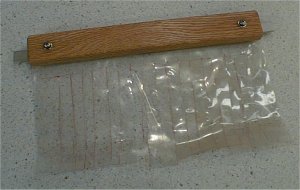 |
| What this rather poor picture attempts to show is a
design for the curtains that would go on either side of the carriage. Basically it is a
section of folded over 8mil vinyl with finger slots cut into it. The curtain is attached
to a block of wood that is in turn attached to the carriage with a piece of aluminum
flat-stock that rides in the carriage extrusion. The curtain is just long enough that it
cannot be folded over into the router bit. Until now (for this picture) I've never had an occasion to remove this device from the Legacy, I guess that is testament enough that it doesn't get in the way. While this doesn't turn the Legacy into a dust free machine (which nothing short of a black hole would) it does quite a good job of locally containing the major debris. |
|
| The standard 100ex model is not equipped with any
convenient method of raising or lowering the bed to any high degree of accuracy. The
factory has a leg kit available which consists of two elevating mechanisms at either
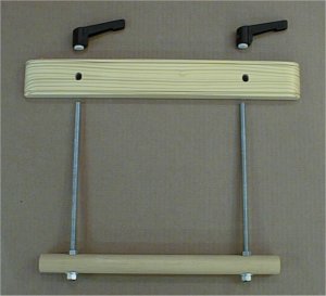
end of the machine along with the four legs and braces; all this for an incredible $400! The factory raise mechanism is basically an Acme screw (one at each end) with a handle that pushes the bed from the center of the ends to achieve the desired height. I was originally intent on creating some device that did the same thing out of a few pieces of threaded rod and other odds and ends. However, the more I used the Legacy and after considering the mechanics of the factory design more closely I came to the conclusion that this was not the sort of arrangement that would naturally guarantee that the bed was aligned in plane with the rest of the machine. As any user knows, it is quite possible to have one side (not talking about taper angle here) of the bed at a height different than the other side (front to back). The design I came up with is basically a movable four post raise mechanism not too unlike that used by planers. The jig consists of a pair of lift devices that form a bridge across the machine. The bed is raised by an arm underneath the bed. The arm has two fixed 3/8-16 threaded rods, these rods are engaged by two levered speed nuts on the bridge. The design is absurdly simple and takes more effort to describe than build, these two devices can be built in a half hour or so. |
|
 |
 |
| The parts for the jig consist of a large dowel (it doesn't HAVE to be a dowel), two 3/8-16 threaded rods locked into the dowel, a bridge piece and two nuts. | This view shows one of the lift devices in use near the head stock end. Another would be used at the tailstock end; that one could most likely be left in place. The one at the headstock end would need to be removed to get the full range of carriage movement near the more critical headstock area. In use these jigs allow for accurate positioning of the bed for very little effort or cost. |
 |
This is another useful improvement for the Legacy, a router collet extension. The Legacy needs long bits to operate effectively; without them, many profiles for turnings and such are either out of reach or one is required to extend the bit farther out of the normal collet than is recommended. This collet extender makes it possible to get the desired contact with the stock when using normal length bits. There are additional comments regarding this device in the review. |
Some time after installing the DigiFence measuring system on my saw, I got to thinking how useful such a feature would be on the Legacy. The reason an electronic measurement system is such a good idea on this machine is that the zero reference on the X axis is not firmly tied to any other feature on the machine. When used as a lathe, quite often some point on the stock behind the headstock is the actual zero point. An electronic system such as the DigiFence allows one to reference zero at any point. Additionally, because the Legacy can be used with other jigs not tied to the lathe functions, zero can be many inches from a previous use. The cursor on the Legacy is also not adjustable. An electronic system is and it allows you to easily account for bit diameters and offsets when you wish to do so. It appeared that the best way to install the DigiFence scale would be to locate it below one of the fixed rails. This allowed the attachment of the read-head bracket on the front of the carriage where it could be disengaged if desired. All in all, the installation was pretty easy. The scale was not quite long enough to get full coverage across the full bed capacity so I opted to install it so I had full coverage at the head stock end where most of the work is done anyway. Note that the addition of the motor drive and measurement system on the carriage shown below limits access to the router for bit changes; this further aggravates that particular problem. |
|
 |
|
The stops for the X and Y axis on the Legacy consist of collars on either side of the carriage split nuts. To set or loosen them you must access a small Allen bolt in the collar. This method while cheap is not that great. For one the Allen bolt head may not be accessible all the time and it requires a tool. To get away from these inconveniences (on the X axis anyway), I came up with a different stop system. Basically it is comprised of a T-bolt through a wooden block. To set the stop one simply sets the block against the carriage and twists the nut tight. The stop shown in this view is the left one, also pictured is the shaft lock used as the stop in the original system. |
 |
|
This is a large flat table for general purpose use with the
Legacy. This can be used to a lot of operations such as Z-axis stock profiling when making
molding and shown installed here is a simple rotary table. The table is about 24" long and is held in place by six dogs which grab the interior slot of the bed rails. The size of top slot in the rails causes some inconvenience because it is a unique size not especially conducive to common fasteners. The attachment method I use allows me to drop the tables down onto the rail and with a few twists of a Phillips screwdriver the tables are down tight. I don't have to try and line up the crews with any hardware inside the rails. For a better view of the dogs that allow this attachment method, look at the bottom view of the tenon table below. |
| Also note in the picture another small table in the lower right. In addition to the larger table I have two small tables that can be installed anywhere along the rail except where the headstock is. These would be used as needed to help support longer stock. Note the 1/4-20 T tracks in the larger table. I am also using a steel 1/2" bushing as the bearing for the rotary table. | |
This is a simple tenon table.
It is basically a 90 degree surface for milling smaller horizontal or vertical surfaces. I
don't use this when I need highly precise joints but it is handy for a few oddball tasks.
The reason I don't use it for precision work is because I have other tools that do a much
better job and are easier to use. One could use the Legacy for joint work with a jig like
this but some careful technique would need to be applied in order to achieve good joint
fits. |
|
 |
 |
 |
 |
 |
 |
 |
 |
 |