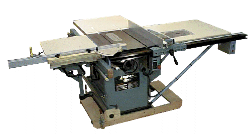
| Materials
This mobile base is constructed of wood, angle iron, wheels and
toggle clamps. The strength and stiffness of the materials used to build the frame
determine the practical length of the base. Metal tubing or channel could be used in place
of wood for the frame if desired. The cost of this particular design is not significantly
less than the Delta base it replaced however it does offer a few advantages. It can be
made to fit a specific machine, the wheel base can be whatever is needed, and better
wheels can be used.
Design
To begin the design of the mobile base there are a few parameters to
consider:
The desired machine height.
This type of base will raise the machine height by a minimum of
about one inch. It could be raised more if desired simply by moving the angle iron on
which the machine rests.
The base size and weight distribution of the machine.
The size of the machine base must be known along with a sense of
its’ weight distribution. This will drive the overall size, placement of the middle
cross frame member, and the wheelbase.
The size and type of wheels to use.
For machines that will be moved very infrequently, hard plastic
or metal “tires” would be preferable since they will not take a set (develop a
flat spot). However, this type of tire will not dampen any machine vibrations. In this
application, a soft (not pneumatic or “cushy”) rubber would be preferable.
The weight capacity of the wheel should also be considered. For example, to provide a good
rolling base for a 400 pound machine, the weight capacity of the wheels (when added
together) should be in the 800 pound region.
Whether or not to use swivel, fixed, or a combination of them should also be decided.
Optimally the frame should also be designed such that it could accommodate either type if
a change was made at a later date.
All the commercial bases I’ve seen have wheels about two
inches in diameter. I wouldn’t consider using anything less than three inches, four
inches would be preferable but a larger wheel will raise the “lift-over” height
of the frame. Although many commercial bases use just three wheels, four is much
more stable. If three were used in the design shown, I would recommend adding an
additional cross frame member onto the front of the frame.
Jacks
Some type of jack device needs to be used to keep the machine
from moving when used. This particular design shows an in-line toggle clamp that serves
this purpose. Other magazine articles I’ve seen use four separate “screw
feet”, these devices are good to use when the load is rarely moved or in order to
level a load very accurately. For a machine base, it would take too long to use them.
Another variation I’ve seen is some type of cam system to raise and lower a board to
which the wheels are attached. Although this method can reduce to component cost of the
system, it adds design and manufacturing complexity; the toggle clamps serve the same
purpose and are much easier to use as well.
Installation
The first issue with installation is due to the fact that this type
of base will have a higher “lift-over” height than commercially available types.
The second issue is how to attach the machine to the base. It could be just set into the
frame or screws could be used to make user the frame and machine are firmly tied together.
If the base and machine are bolted together, the vibrations will probably be less. The
exact configuration of the machine base may control how it can be attached.
Back
to the Unisaw Index page |
