|
|
|
Unisaw Sliding Table Modification
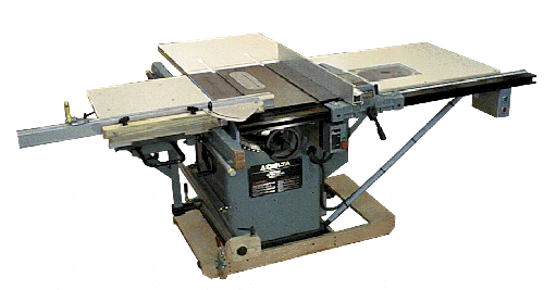
This picture shows
the sliding table attachment and the rest of the tablesaw in its entirety. In addition to
the sliding table attachment, there is a custom mobile base, a folding outfeed table, and
a custom extension table that has a router plate in it. |
 |
The
Problem Crosscut Sleds The problems with these devices are:
Sliding Tables Modifications The modification to the table and fence are fairly easy to do and do and make the sliding table much more useful that the OEM unit. The modifications dealing with the sliding mechanism utilize a thick steel adapter plate which would be a more difficult to fabricate part. The primary benefits of the modifications described herein are:
It would be possible to perform only those modifications that did not require the adapter plate. The remaining modifications dealing with the crosscut fence and table will greatly improve the usability of the original system. Accuracy and Performance Improvements
|
|
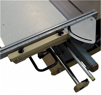 |
In order to solve the fence
recalibration issue, it was necessary to make the pivot point of the fence
stationary. The method used to accomplish this was to use a fixed pivot arm that the
fence is attached to. The wooden pivot arm is secured to the sliding table via two Tee bolts and the plastic knobs on the top of the pivot arm. The fence itself is attached to the pivot arm via the aluminum miter plate. The miter plate will allow the fence to pivot through an arc of -5 through +50 (cw) degrees relative to the 90 degree home position shown here. The fence cannot be placed in both the forward and aft positions as the OEM unit can. With the fence in the aft position this limits the crosscut capacity to about 27 inches. If it would be more desirable to have the fence in the forward position, this mechanical concept could be flipped giving a crosscut capacity of about 36 inches. |
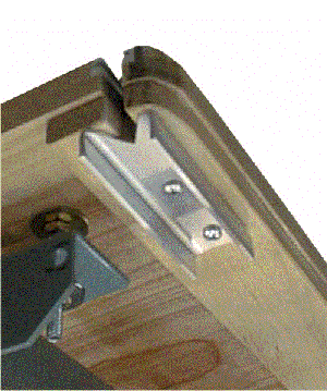
| The metal bracket in this view is
the stop for the X axis pin in the pivot arm of the fence assembly. This stop
bracket constrains the fence assembly in the X axis to keep the measuring tape calibrated. The metal plate is not a precision piece nor is its location very critical. However, it is important that the X axis pin does not contact any component other than the Vee groove of the plate. The fence assembly is not attached in this view. |
 |
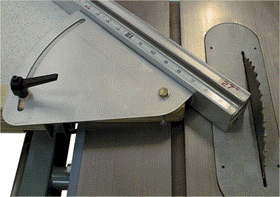
| This is a close-up of the fence assembly near the pivot point. The pivot bolt is a 5/16-18 bolt that is jammed from working loose from rotation by a 10-24 screw seen immediately behind it in this view. Both the pivot bolt and the miter lever bolt have Teflon washers to reduce friction. Because the OEM measuring tape supplied is not as readable as others. A 1/2" straight bit in a router was used to mill the fence channels so that they would accept a 1/2" replacement tape. Although the miter plate is made of aluminum, it could have been made of 1/2" plywood.
|
 |
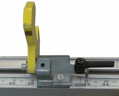 |
The OEM cursor on the stop block
is a fin type which will obscure half of the reading on the tape measure; a reticule type
cursor allows both sides of a mark to be seen and is inherently more accurate. A new
cursor was made out of clear plastic and attached to the body of the stop block.
|
| The lower guide bar is attached to the saw cabinet via two 3/8" studs that are cantilevered out from their supports by about 2 1/2 inches. In order to transfer the lower guide bar load properly to the cabinet where it belongs, two small wooden wedges are used underneath the 3/8" studs. | 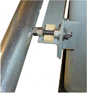 |
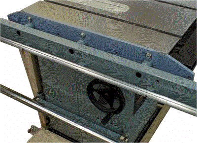 |
In the OEM design the top bearings control too many settings of the unit making alignment an unnecessarily complex trail and error process. The guide bearings control slide friction, table height, and table slope. One way to improve upon this situation is to de-couple the table Y and Z axis positions from the sliding carriage and its attached bearings. |
| In order to do this
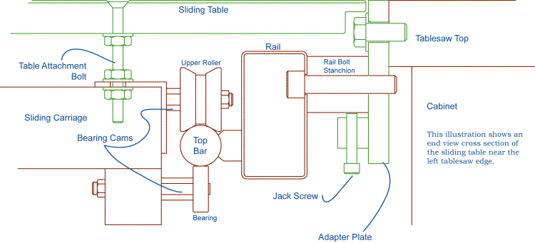
easily the rail and top bar are lowered by 1 ½" using an adapter plate.
Lowering this assembly also allows the table surface to extend over the rail (p/n 1347667)
to the edge of the saw table. The lowering plate also incorporates jack screws placed under the rail bolt stanchions that are used to very easily adjust the top bar assembly parallel to the tablesaw surface. The adapter plate greatly simplifies the installation and alignment of the sliding table. |
|
| In order to keep the sliding table working smoothly, the guide bearings must be free of dust on their contacting surfaces. Since the OEM unit did not come equipped to deal with this, dust sweepers were installed. The sweepers are installed to the underside of the table. They are made of one inch nylon paint brushes that have a semi circular pattern cut in the bristles to conform to the top guide bar. The handles have been cut off and they are mounted to a 1 1/2" angle bracket using a bolt in an elongated hole for adjustment. Lowering the top rail assembly makes the installation of sweepers much easier but it could be done even without using the adapter plate. Sweepers could also be used on the lower bar but there isn't much benefit from doing so. Visible in this view is a 1/2" thick support used to strengthen the table in the area of the T-slot. |
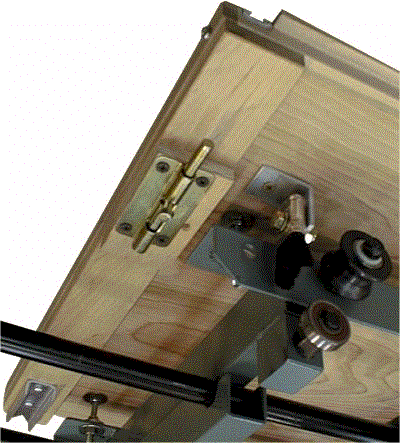 |
| The OEM unit is designed with a carriage stop at the beginning of its travel. The reason for locking the table in this position is to prevent the stock from being cut prematurely when loading the table with the saw on. I preferred to lock the table even with the saw table infeed edge. A common door bolt latch is used to keep it in this position; the pin end will engage a hole drilled in the top rail. | |
Once the top bar assembly has been installed and made coplanar with the saw top, the lower bar is installed. With the two guide bars installed the sliding carriage (without table) is slid onto the guide bar. The roller and bearing cams are adjusted so the carriage glides smoothly without any slop. The bearing cams do not need to be adjusted for perfect parallelism to the saw since the table can be adjusted independently via the table attachment bolt shown. The image below is a cross section of the sliding table along the left edge of the saw table, all the items in green are new fabrications described in the article, all others are the existing Delta components. |
 |