|
|
|
 |
 |
 |
 |
 |
 |
 |
 |
|
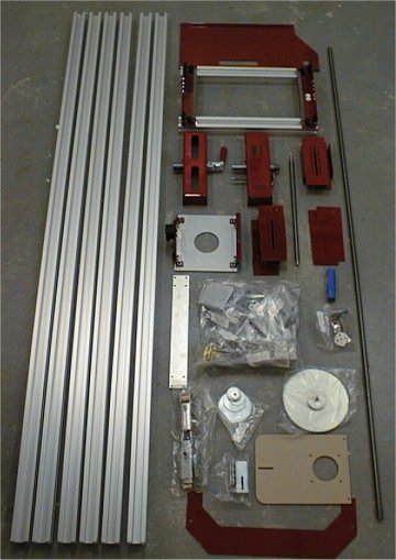 |
When the machine arrives is just a bunch of parts, 99% of the assembly must be done by the owner. Working over a couple of days I was able to assemble the unit in 4 hours. The assembly is broken down into logical stages, each stage has an associated bag of parts. Separating the parts into bags this way is a great idea, otherwise a great deal of time could be spent hunting for the right part amongst the hundreds of individual items. I encountered very few problems when putting the machine together, I did have to make the X axis screw block holes larger to allow the shafts to fit into them. Nearly the entire machine can be assembled with the three Allen wrenches supplied with it. This isn't an accident since these wrenches are the ones used to configure the machine as well |
Pictured at right is the "transmission" for the Legacy. Both of the big gears can be replaced by other optional ones that would give a 2.5x and 0.25x multiplier to the ones seen here. At this point I believe the ratios that come as standard will work pretty well for me. The smaller gears laying on the rail are some of those that go on the end of the drive screw just before the crank handle. Laying loose on the head stock is one of the directional gear assemblies. These gear assemblies are bolted onto the driveline to get the stock to rotate either left or right to coincide with forward movement of the router carriage. |
 |
It is not real convenient to have to mess with all these gears and such to configure and reconfigure the machine but this sort of manual design is what keeps the cost down. Some clever user could probably come up with a dual motor system that would eliminate all of this, hmmmmmm. Also visible in this view is the index pin. When needed, this spring loaded pin can be used to move the head stock by a fixed amount of angular rotation. A metal clip like a screen door shock stay is used to hold the pin away from the index holes in the gear when desired. |
|
 |
At left is a view of the head stock viewed from the end, the "lathe drive package" is fitted as well. The term "lathe drive" simply refers to the second crank handle attached to the head stock. This is the setup one would use to turn stock round, the router carriage and head stock rotation are not coupled in any way. The "cut-off" piece laying on the head stock is how much I removed from the drive screw crank handle (1 1/8") to keep the two crank handles from hitting each other with the machine configured in this manner.
|
This is a view of the head stock. I have attached (by magic) one of the metal devices used to "chuck-up" stock into the mill. These metal stock centers are screwed onto the end of the stock. The four tapered post then fit into any of the 12 slots on the head stock face plate. I don't know if the Legacy people invented this method of attachment but it is pretty clever. Four of these stock centers are included with the mill, it should be five, I bought six extra ones and highly recommend any owner to do the same, they don't cost much.
|
 |
 |
The tail stock on the legacy is unlike that on a lathe. It is positioned and secured into place using two bolts that clamp the assembly to the bed rails. The tail stock center is moved into position using the toggle clamp. The center provided is a simple point which fits into a standard tapered sleeve, this would allow it to be changed to some other standard lathe accessory like a drill chuck, live center, or jaw chuck.
|
The router carriage is guided and supported by the outer rails, it rides on plastic bearings as well as felt pads. Overall the design is fairly simple. The router is positioned in the Y axis in a similar manner. The router is bolted to the plate and moves on its carriage between two rails. The carriage is moved using an acme screw and split-nut system, the positioning stops are clamping collars locked in place with an Allen head screws. When the router is moved back and forth in the X axis there is some slop in the system, unless one attempts some very tight tolerance joinery this slop should not be an issue.
|
 |
 |
This image is a close up of the router carriage and the split-nut that couples or de-couples the carriage to the drive screw. The carriage has a crude cursor to read a crude tape measure that can be used to position the carriage in the X or Y axis. The tapes are adhesive backed, there is no way to align the cursors to them. If there is one obvious improvement that could be made to the machine it would be the ability to align the cursors or better yet to have a moving scale much like those used on the Incra. |
There isn't a lot of precision in the measurement indicators. As such, (and as mentioned in the review ) the machine is more suited for operating in a "free-form" mode. Since I bought the 1000ex, the factory has introduced a couple of accessories one of which claims to be a jig suitable for mortise and tenon operations. Given the relatively low accuracy and repeatability of the Legacy as a whole, I would foresee there being a lot of problems in trying to achieve the kind of 0.005" accuracy one would desire of M&T operations with this machine. The aspects that make me dubious of this capability are:
More clearly visible in this close-up is one of the stops on the drive screw. The stops have to be locked down fairly tightly because the when using the crank handle there can be quite a bit of force applied to them when they are run into. Using stops like this also limits them to a single position on either side of the slip-nut, that means only one setup can be retained at a time. I haven't found a situation yet where I needed multiple stops but that certainly would be a nice capability to have. |
|
One nice feature of the mill is the ability to do pattern work, this can be done on circular stock and flat as well. Two brackets are provided that are installed onto the back rail and can be used to hold patterns. A guide pin (not shown) can be fitted to the router carriage to follow a pattern. To do this there would have to be a little synchronization between the pattern and the stock (which is to be expected). The guide pin bracket can be seen in the parts image near the top of this page, it's the tan colored plate. The plate is actually clear plastic though. |
 |
If a pattern were long and thin these two brackets alone may not be enough support. Also, the way they are locked into place is somewhat inconvenient, especially if the machine were up against a wall. Some improvement could be made in this area and it would be possible to build additional (and / or better) brackets if needed. |
|
 |
 |
 |
 |
 |
 |
 |