|
|
|
Back to the LittleRat Index Page
 |
The Mortise Rail |
 |
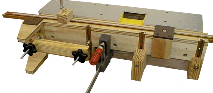
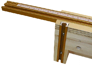
This is a view showing the left end of the MR, the rail is made primarily of 1/2" plywood and a few scraps. The rail is basically the same cross section as described in the manuals but a little thinner. The vertical members are also wider to accommodate more surface for whatever may be affixed to the rail. Having the top track extend beyond the jig is no accident, it allows attachments such as the stops to be installed and still allow the full face of the rail to be under the router base section. |
 |
|
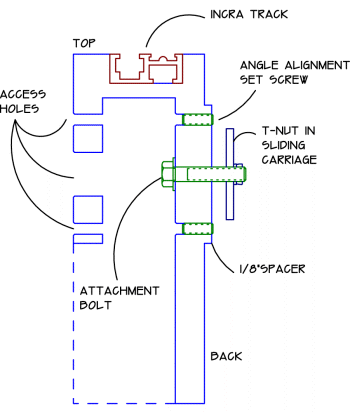
This view is of the back or the MR, note the 1/8" thick hardboard used as a spacer to hold the MR away from the chassis. The rig must be spaced away from the chassis otherwise when it is clamped down it would be immobile, this is because the sliding carriage is slightly below the plane of the chassis. The whole rig is affixed to the Rat by using a large T-nut that runs in the slot of the sliding carriage. Here I'm using 1/8" thick steel flat stock which I have cut to size and installed three 1/4-20 threaded inserts. |
At right is a cross sectional view of the mortise rail; the section is taken at a point between the vertical track stations where one of the three attachment bolts are used. It may not be intuitively obvious but this whole assembly needs to be aligned once installed. The sliding carriage on the Rat has a little bit of slop in it that is magnified when you install (or clamp) things to it. I've made provision to align out any induced angle by making a 10-32 threaded hole above and below each 1/4" bolt hole. This allows any error in angle to be corrected using set screws (which push against the carriage); only one setscrew at each bolt location would be required. |
 |
| My thanks to Incra for providing the T-track used in this project.
|