|
 |
 |
 |
 |
 |
 |
Building a New Woodworking Shop
|
|
|
|
|
|
|
Construction
| The following is a pictorial essay on the major elements of the building process. More detail can be found in specific subject articles. |
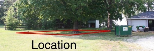
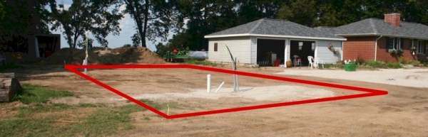
| Location is critical to the success of many endeavors. The new workshop location was much harder to resolve than I had anticipated. Although the lot on which it is placed is large, there were limitations regarding setbacks from the lot lines and road, convenient access to power and utilities, and integration / influence with existing structures. When it came right down to it, there were two "best" positions for the shop on either side of the house, one on the east and west respectively. | |
 |
The eastern location offered a better path to the house, synergy with the garage and its hard-scaping. The down-side was more trees to remove. |
| The west location offered a better view, possible tie in to the existing sewer, and more elbow room. The down-side was a longer electric run and site dominance. | 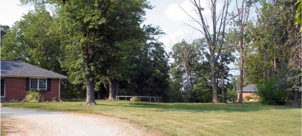 |
| In the end the eastern location was selected because the building would dominate the site less, it blocks and isolates from a specific view, and seemed to integrate into the existing structures better. |
 |
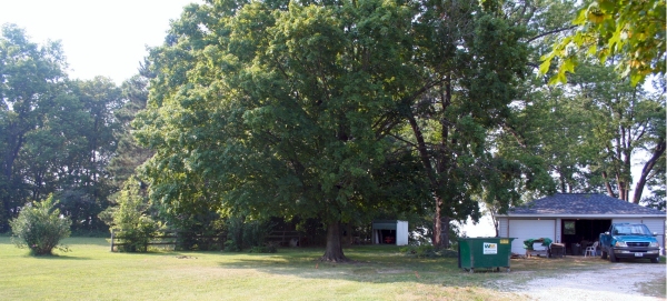
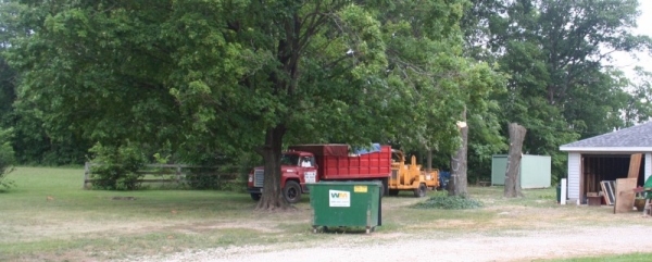
| Work actually began with cutting several trees. In total, 5 trees had to be removed as well as another that was in just bad condition. Of these only one was a good tree in a good location which we really hated to remove. All the others would have need to be removed sooner or later due to death or decay anyway. The one "good" tree is the one dominating the view in the picture below. I had all but one of these removed by a subcontractor. |
 |
| I wanted to have water, LP,
electricity, and perhaps some other lines like telephone run out to the shop. The
electrician I consulted suggested running a new connection from the utility pole to the
shop and feeding the house and garage off of that as opposed to running power From
the house To the shop. This seemed to be a much better approach because I
wanted to eventually change the fuse panel and meter location on the house any way. In order to do this I needed to have a long trench dug with a couple of small branches. With help I laid two water lines (black), a gas line (yellow), and two 2" conduit lines. These were laid in a bed of sand below the frost line, covered with a layer of sand and then filled with a mixture known as "CA6" or "roadmix". All of this was tamped down with a portable gas powered tamper. As the conduit was run, number 2 wire was inserted with each section. This size of wire is actually beyond the realistic capacity of the conduit size used. It was a little larger than what the electrician spec'd out but I got a good deal on it. Running it in place as opposed to trying to pull it was key to getting it in. The other conduit was empty except for a pull string. The plastic gas pipe had to be terminated with a special metal fitting to avoid having the plastic pipe exposed where fire could get at it. |
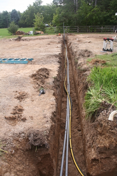 |
| This trenching was a lot of work much of it done in the rain and mud. We were EXTREMELY happy to get all this mess behind us. I planned the shop location out in CAD to ensure it would work with the building and such. I used the builders plans to double check the pole locations so that the trenches would all run clear of them and that the conduit would come up in the east wall. In the middle of the picture you can see my little green monster that made this literal mountain of work easier than it would have been otherwise. |
 |
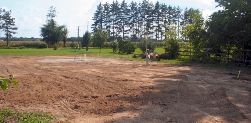
| September 6, 2006 With the site ready, major construction can begin. All the utility trenches have been covered and the site is smoothed out ready for the building crew to arrive. |
 |
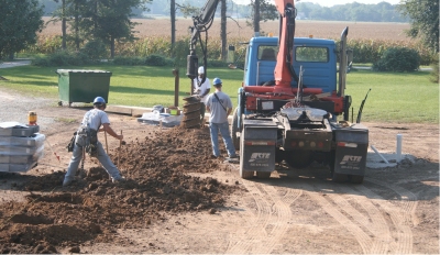
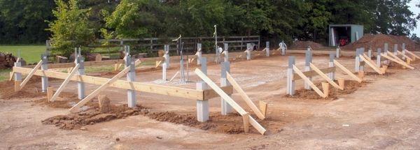
| September 8, 2006 The building materials arrive on a flat bed semi. The tractor is equipped with this crane gizmo the driver used to unload and carry materials into the work zone. This same crane is outfitted with a hydraulically powered post hole digger. The Forman laid out the building as per my specifications and then each hole which was then dug by this machine. This tool made extremely short work of this task, it could drill a hole usually in less than a minute. |
 |
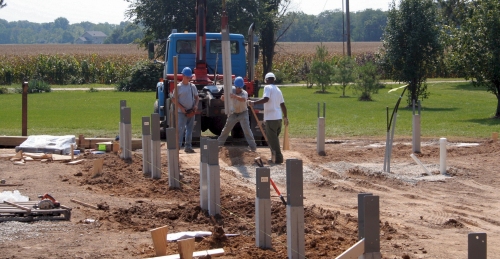
| After the post holes are dug, a
concrete truck was called in which poured a pad into the bottom of each hole.
Thereafter, the crane was used again to set the posts in place. The posts were placed somewhat roughly, they would be trued up later. |
 |
 |
|
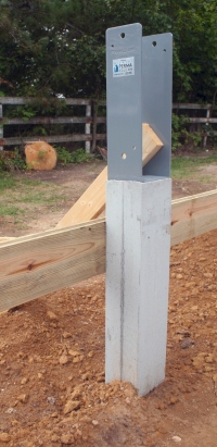
| Notice that the posts set into the
ground are not the typical treated wood post that are prone to rot off. These are
special high strength, re-inforced concrete posts with metal brackets attached to the
top. There are also uplift resistors attached to the bottom of each post. I
never considered using normal poles set into the ground, instead I got quotes for this
type of method or a pole building set upon a stub wall foundation with footing etc.
I believe this concrete column method does quite a bit to keep costs in line with the
basic pole barn concept. These poles are not cheap but still reasonable I think. They are also not proprietary to a specific brand of pole building and can be bought through a dealer network for about $65 - $85. These particular products are sold under the name of Permacolumn. The rim board was directly attached to the columns the top of which is about 4 inches above the height of the interior floor. You can see that I will need a lot of fill to bring the grade up. |
 |
| September 24, 2006 After the Permacolumns are placed, the building crew pulls off until the concrete pad is poured. The building did not have to be constructed this way but this was the method recommended by the building rep. I needed to create a foundation skirt under the rim board and chose to use rigid foam for this as opposed to additional rim boards which is more typical. |
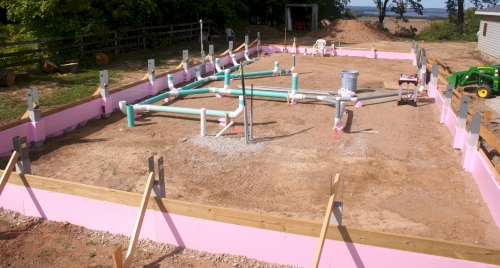 |
| In addition to this
bare foam, I considered a pebble covered foam product, synthetic rim boards, and
foundation grade treated boards. I went with foam due to cost and to increase the
perimeter insulation, time will tell if this was a good choice. The exterior will be
covered with a stucco like product. There is also a layer of foam on the inside of
the rim board set to the height of the slab. This had to wrap each column to provide
a thermal break. This (also) was a lot of work. Also seen in this picture are the dust collection pipes run under the slab and some additional conduit. I altered the DC pipe layout a little over what is shown in this picture. Setting the pipe was fun at times but not that much fun; partly because I was racing the calendar at this point trying to get ready for concrete. Since the pipes were underground, I decided to pitch them to a drain., that is why it looks lower at the North end, it is. |
|
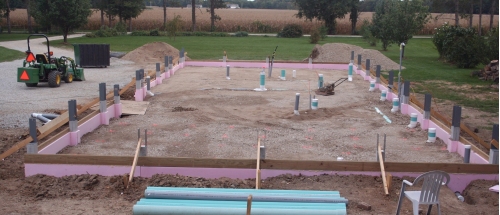
| September 27, 2006 After the DC pipe and conduit is in place, the fill starts to go in, I used about 75 tons of CA6 set in lifts and tamped down. I was worried somewhat that the tamper would break the DC pipes, I didn't dwell on them and they seemed to take the abuse just fine. |
 |
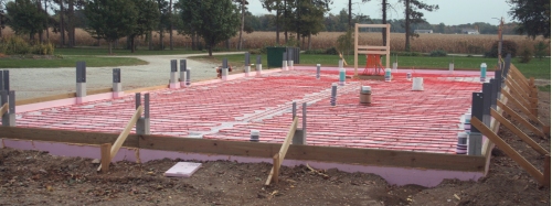
| October 9, 2006 All of the hydronic heating tubes have been laid on top of rigid foam insulation, the manifold is attached and the site is ready for concrete. Putting this insulation and tubing down was a lot of hard work. I had to race the clock quite a bit to be ready at this point. Fortunately I was able to take full and half days off from my real job in order to put extended hours on the project |
 |
| I had some help in getting the project to this point as well. My dad, mom, wife along with a little bit of help from some other folks here and there all contributed to getting the job done. Quite a large portion was done by my lonesome though which made progress slow. | |
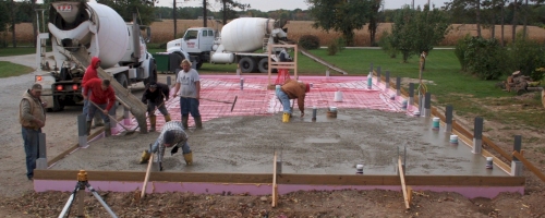
| October 10, 2006 A cool overcast day and concrete is going in. The 7 man crew laid it down in fairly short order. They shot the grade using the insulation I installed at the rim and a laser system as well. In all, 4.5 trucks or 34 yards of concrete were used |
 |
At the end of the day the pour looked pretty good. The crew cut 1.25" deep control joints in it while the crete was still green. Cutting is a big risk with this heating tube in the concrete, the alternative is to put no break lines in and let it crack with no attempt at control or to hand tool joint lines in. I chose to accept the risk. I watched the pour and it didn't look like the tubes were lifting much if at all so it looked to be like a good bet. When done, the floor appeared to be pretty flat visually. It actually isn't real flat and you can't really expect that it would be. The concrete man explained it to me like this, "Jesus doesn't pour concrete, he has other more important s#&@ to do"! |
|
| The wire mesh used to hold the tubing in place doesn't really add any strength to the slab because it is sitting at the bottom. Some people pull the mesh (and thus tubing) up during the pour but this is generally a bad idea because then you have far less control of where the tubes actually are and the risk of hitting one with a saw goes WAY up. Some people have laid mesh on top of the tubes to get around this problem but that adds measurable cost and effort. | 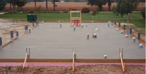 |
| A more common solution is to use fiber mesh concrete which is basically glass fiber added to the recipe. I've used this in the past on concrete jobs and prefer it. The product will leave the surface just a little fuzzy but the fibers sitting on top eventually burn off. I didn't apply sealer to the pad because I am unsure at this time what product I might use as the final surface covering and some products are not compatible with sealers. | |
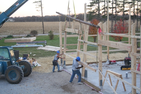
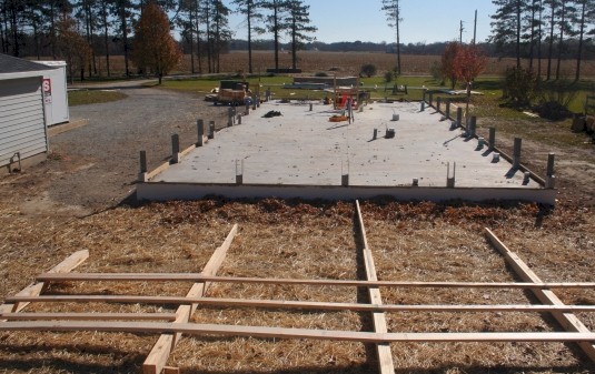
| November 9, 2006 After a suitable delay to allow the concrete floor to harden, the pole barn crew pulls back onto the site and starts to lay out the walls. The weather was unusually warm for this time of year making this a good day, as it would turn out, this was the best weather day the entire time they were on site. There were over a dozen guys on site at one point, I think members from three different crews. They were thinking they could crank this building out in about 4 days. |
 |
| I assumed they would start by installing the poles and build the rest of the frame off of it, that isn't how it was done though. They built the wall frame in sections which are then lifted in place. These frames were built near where they staged materials or anywhere else there was some free area but not on the nice flat concrete surface (which I assumed would have been handy for this). | |
|
| The wall frames go in with a lot of
muscle and help from a telehandler (a kind of four wheel drive off-road fork-lift).
You might be able to detect that the garage door header in the section they are placing is
too high. They discovered this error and corrected it the next day. At the end of this day I had something that was starting to resemble a building. The true size of the structure was also becoming apparent, kind of bigger than I imagined at least on the outside. It was already clear that the structure was going to dominate the home site; I'll have to plant some trees or something to try and reduce the impact. |
|
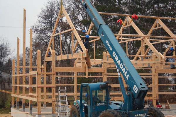
| November 10, 2006 Another framing day, the weather is turning colder and there is a continual threat of rain now. The company I went with for this seemed to have instilled a certain level of safety consciousness in their crew. I can't remember a time when these guys were working high and were not strapped off. That's what the orange gizmo's are at the rook peak. I think they even wore hard hats the entire time they were on the job. You can see here they are setting the roof trusses by machine. These trusses are double laminated 2x12's with at least the bottom cord an engineering rated wood. They are eight feet on center which just by looks appears to be a bit far apart to support the desired load. I specifically asked for a residential load rating on the second deck and these are (according to the plans provided) capable of supporting that. |
|
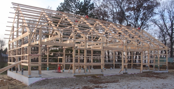
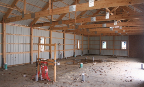
| November 12, 2006 Another framing day, the weather wasn't too bad today and most of the rough framing is completed. It's easy to observe the framing structure of a typical pole barn here. Large poles carry the weight of the building, horizontal members provide the framework for the siding and roof system. A typical pole barn in this area has a 4/12 pitch roof, this one is 9/12 pitch, a bit unusual. Viewable within the attic area are several cross pieces used during construction that will be removed later to free up the attic space. Aside from one, maybe two guys, most of the crew working on this job were fairly "new" and did not have any experience building such a high pitch roof (on a pole barn). The pitch is too high to walk as the tin would be way too slick a surface for that. As I talked to the crew their concerns about working this high a pitch was mentioned several times. |
|
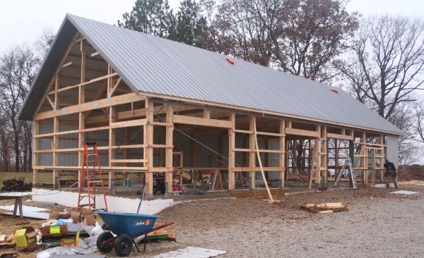
| November 13, 2006 Cold, rainy overcast and basically miserable, couldn't even take a good picture of the thing today. The crew put on quite a bit of the roof tin in weather that would have sent me packing. It reminded me why I was paying to have this done instead of doing it myself. As can be seen by the evidence above, despite their concerns, the crew was able to put the roof tin on. They basically walked the rafters and put the tin on by their side. These sheets are the full length of the roof and had to be hand punched to place each screw. There are two common methods of putting tin siding on like this. One is to nail it on the other is to use screws. The company I went with uses screws (on both side walls and roofs) which is better I think. In addition to that, there are two common fastener location methods, putting them in the flats or on the ridges. These guys put them on the flats with additional ones on the ridges where panels lap one another. November 14, 2006 |
|
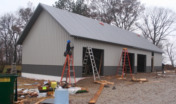
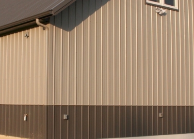
| November 15, 2006 Most of the wall tin is on now. Note that the tin isn't cut for the window rough openings before being installed. There is a lot of trim to this type of siding which kind of makes for slow going at times, kind of like vinyl siding. You can kind of see the general mess everywhere, the entire yard was pretty much this way and the weather only made things worse. The tin used by this company (and at least one other I know of) is not the standard stuff available at the national big box chain stores. It is coated with Kynar paint which is supposed to be quite durable and fade resistant. |
|
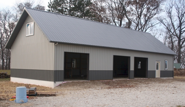
| November 17, 2006 Seven working days later, the shell is up and complete. The crew installed all the walk doors and windows but not the garage doors. These would have been subcontracted out by them anyway but I planned on putting them in to save a few bucks. It might not appear so in these pictures but the structure is a bit larger than I imagined and tends to dominate the immediate area. It's too late in the year to do any landscape work; I'll bring the grade up a bit around the building, that should help some. As it turns out, I'll have to re-grade the entire yard, the telehandler really tore it up and made a lot of ruts. Although the building crew did cleanup the area a bit before they left I did have to diligently search for loose nails and screws laying on the ground. Over many days I would find several pounds of nails and screws about the exterior. I'm trying to find these now as opposed to next spring when they'll probably be intent on puncturing the tires of my little green monster. |
|
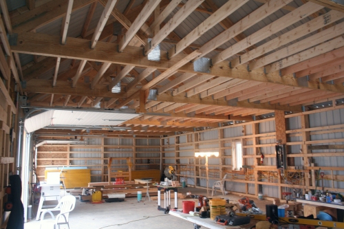
| Here is an interior shot. On
the inside it's pretty basic. There is no structure for the attic or a frame on the
walls to hang anything - just a bare bones shell is what I have at this point. This
is what you get for about $31k. The total cost at this point is of course more than
this, the concrete alone is several thousand. I am about two months behind my
original schedule at this point, I didn't really have a good timeline laid out for
this. If I had not contracted this phase out and did it myself I could have started sooner but I believe I would have been caught by the weather and at this point been much further behind. During the seven days the pole barn crew was on site for this phase, they probably expended about 350 man hours. On a good week I can get about 36 man hours in on a project, most of the time less. What they did in 7 working days would have taken me over two months assuming I would be as productive (probably not a good assumption). |
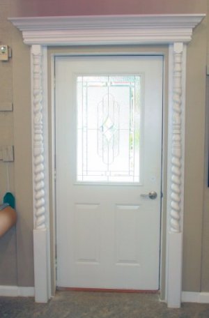
November 26, 2006 The doors I purchased are commercial grade with (supposedly) an R12 insulation rating. I found these to be quite a bit easier to install overall than typical residential garage doors and I really like them; in fact I would not want to put in any thing of lesser quality than these. |
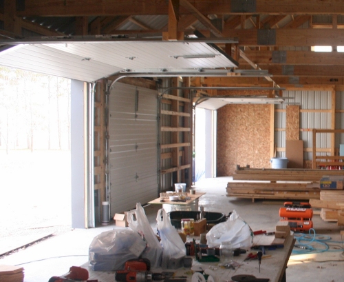 |
| I'll probably come to regret not getting windows in these doors; perhaps I will be able to add them later. When the Attic joists and deck goes on I'll support the door track a little differently than shown here but for now this will be fine. At this point in the project, I should have started working on the heating system. I didn't and would later regret that decision. | |
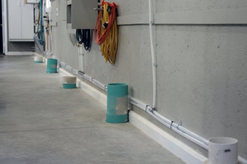
November 29, 2006 I'm pretty sure that if I had went with an ICF wall I would not had had the forethought to have provided for a wall penetration for all of these exterior devices. |
 |
|
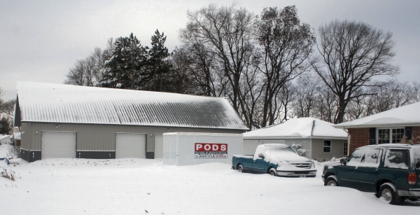
| December 1, 2006 Snow bound! Our first snow of the winter and it was a good one. This impeded progress on the shop a little bit, I'm glad I got the overhead doors on, at least I was able to button up the shell. The street and side roads were impassable for the entire day; I wouldn't even be able to get out of my own driveway until later the next day. Along with periodic mail box replacement, this is one of the perks of living out in the sticks. |
December 6, 2006 I used a small kerosene heater to keep from freezing to death. The heater isn't really big enough to heat the space much but it will take the edge off and I found it useful for warming up tools and other items so they wouldn't suck all the heat out of me when I handled them. A framing nailer came in pretty handy for this work, especially since I was doing this mostly alone. I decided to simply put the framing members on horizontally in typical pole barn fashion as opposed to erecting a typical stick built vertical wall or running the horizontal 2-by's flush within the poles. I originally thought this method would be easier than the other options, in the end I don't really know if it was or not. I don't know how much this will help but behind each framing member where it attaches to the pole or other support is a piece of 1/2" foam to create a thermal break. Later I installed some more framing where needed for electrical boxes and blocking on the poles where the ends of the interior sheeting will land. |
 |
| At this point I was
ready to have the insulation blown in. Due to technical problems, the contractor I
had lined up was unable to come in and do the work so I went ahead with other phases in
particular the wiring. I thought it might be good to have all the wire on the walls
prior to this anyway. The insulation contractor assured me the problems were being
resolved and he could insulate the building within the next few days so I wasn't too
concerned. At one point I noticed several small leaks in the roof and had to call the framing crew back in to fix the problems. These were caused by screws not hitting the roof purlins and a few stray holes. I'm not sure what they did but the leaks went from about a dozen down to two. |
|
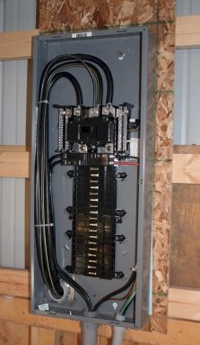
December 18, 2006 The original service ran from a pole overhead into the house to a fuse panel. I had wanted to change this fuse panel out to a modern circuit breaker panel and this became a good time to at least set the ground for that. To that end, I decided to re-route the power to come into the shop first which would then feed the house and garage. With the main feed at the shop, this makes all downstream electrical panels effectively a sub-panel. The breaker box in the shop contains a 100 amp and 60 amp 220v breaker for the house and garage respectively which then will distribute the juice into sub-circuits with their own breakers from thereon. |
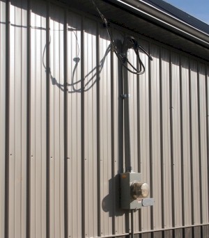 |
It took an electrician and a helper about 6 hours (12 man-hours) to hook up the wire I had run into the three breaker boxes, install a new meter base, and move the meter and wire from the house to the shop; this cost me $1188. I've never run big wire like this before and really didn't want to change over the main feed since there is a great risk of getting electrocuted so I decided it would be better to pay someone who knew what they were doing and had done it before. After seeing the guys change the wire over, it didn't look to be too hard, they did it hot too; still don't think I would do it though. I could have put the meter base and weather head on, I don;t think I would have save much though. In this picture the big wire coming in can be seen as well as the two breakers to the house and garage. The box itself is a Square D QO type running just over $200. I was convinced to go with this supposedly better box compared to the GE of CH brand I was originally going to get. The electrician liked this box, I'm not very impressed by it. There is literally nothing to these things; I consider this one to be a little too "plastic-y" compared to the cheaper GE & CH units. The job of a breaker box is to hold breakers though and hopefully the QO series is better than the typical CH, GE, or SD HL line which are about 50% of the cost of the QO breakers. I'm already pretty skeptical about the quality as I have already had one of the 20 amp breakers fail on me. |
 |
| While present, I gave
the electrician a quick run-down of the electrical plan and got a couple of interesting
comments. The first was that the SD Homeline breakers would fit into a GE breaker
box. The second was that they have replaced EVERY single Arc fault breaker they have
ever installed within about 2 years of service. I planned on using 3 of these
breakers and since these things are expensive this was not good news. I also plan to
install 2 GFI breakers, he said these didn't fail near as often. December 27, 2006 |
|
December 30, 2006 This was a nice reprieve since it was quite cold while I was running all the wire. It's good not to be running off of an extension cord too. My brother helped me install all the ceiling joists, each one was hung with metal joist hangers. The joists themselves are 2x6 spanning just under 8' and hand nailed into the trusses. |
 |
| I had purchased a palm nailer for this purpose but found this to be pretty ineffective and slow compared to nailing by hand, this is one of the very few disappointments I have had in the way of tooling on this entire project. We used a long 2x10 hung between two step ladders as scaffolding and ran the joists 16" oc except at the edge which ended up being about 24". We accomplished this in about 3 partial days. | |
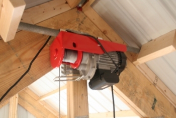
January 6, 2007 51 of the 56 sheets were brought up using a temporary hoist. This made a HUGE difference in the amount of effort needed to get this job done. About half of the sheets needed to be cut but the 8' oc trusses made the cutting pretty minimal. |
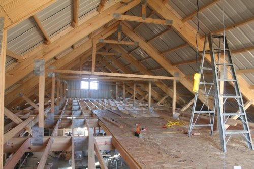 |
I installed an electric hoist temporarily for this part of the job. There are two metal loops on the top of the hoist chassis and a pipe is run through these and cut to length to fit up into a couple of the roof purlins. I used a simple rope set-up to haul a sheet of plywood up as needed. I had always planned on using a hoist in the attic even if I did not have a walk-up space to haul heavy items up for storage. It seemed logical to just go ahead and get one now to help me build the shop. I picked this unit up at Harbor Freight for about $90, seems to work pretty good. |
 |
January 10, 2007 |
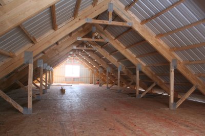 |
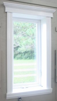
I threw a curve ball at the metal building crew by changing the two 30" window units for a single 60" double window at the last minute. I thought these guys would have been able to figure out how to compensate for the change pretty easily but they didn't really. I let them go ahead and put it in and then cut out the center pole and added a header to compensate. The window looks much better this way and I can actually open it which I could not do they way they had installed it. I also was able to caulk around the several of the exposed screws threads and holes as these were now easy to get to with the deck on. I'm hoping this will take care of some roof leak issues. I was getting somewhat accustomed to the open feeling my un-decked attic gave and wondered how closed in it would feel once the deck went on. This picture can;t really convey that feeling but basically I am quite happy that it didn't feel like the sky had fallen down. With the attic floor on, the space is more "cozy" but does not have a closed in feel to it; I am really happy that I went with the 10 foot side walls. The attic floor is also the ceiling for the ground floor. I chose not to put a finished ceiling on for a couple of reasons. The first is effort. It would take 56 sheets of material to cover the entire ceiling and I loathe working overhead. This work would be nowhere near as easy or quick as putting the attic deck on. The second is cost. Using the cheapest materials would have run about $500. I would like to have a silver tin ceiling, that would run about $900 or more. The down side of not putting up a finished ceiling is that is will not add much reflectivity to the overall lighting. To improve that I plan to paint everything white, a power sprayer ought to make this task not too difficult. I figure I can always go back and put a tin ceiling on later if I really want to anyway. |
|
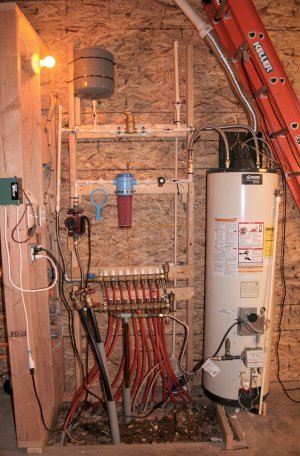
January 26, 2007 The plumbing may not be the prettiest but it does the job. After becoming more familiar with the technology I'm sure I could do it much better and quicker a second time. I may change some minor aspects of the design later, I might also re-do the plumbing if I ever run out of stuff to do. I had hoped to have the shell insulated by now but that isn't the case. My insulation subcontractor has basically not come through for reasons not detailed herein. That means I'll have to get more bids but since the weather has turned cold I may find that it is too late to even get this done until spring unless there is an unusual warm spell or something. Good insulation makes all the difference in the world in trying to heat with this type of system. |
 |
March 6, 2007 I ended up on my back with one leg pinned inside the ladder rungs, fortunately I wasn't completely disabled nor passed out. Long story short, I got bruised up pretty bad in a few places and cracked by left heel. I was on crutches for a while and had to wear a cast for quite some time. |
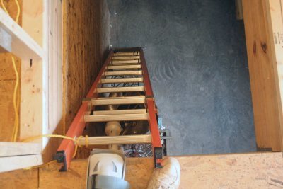 |
| If I had taken the time to tie the ladder off to begin with like I should have (as it is now) I would not have had this problem. Overall, I consider myself quite fortunate, a fall from that high could have been a great deal worse. As is, a few doctor bills and lingering pain is a suitable reminder of the price one pays for being stupid. | |
March 12, 2007 There is something I didn't anticipate. The stuff kind of gets all over when they spray it. The crew did mask off the windows, doors, and floor edges but it still gets on lots of other stuff. The foam also leaked out of the building in a few places. The crew didn't do a stellar job of cleaning all these leaks off either. The particular foam used goes by many names, I forgot what the exact chemical recipe is but basically it is the "soft" foam type sprayed 3" thick. Soft foam is the best choice for metal buildings because it is more compatible with the expansion and contraction typical of the skin of these structures. It has another benefit in that water will run directly through it. That way, if there is a leak, you will know where to find it. This is the reason that some insulation contractors will not spray anything else on roof interiors. |
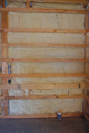 |
| The walls of the
building are actually 8.5" thick and in application the foam ended up being thicker
than 3" nearly everywhere. This is mainly because (so it seems) that the
minimum thickness is fairly hard to control. In the end, nearly all the wiring ended
up being covered and after observing the remaining space I am glad I did the wiring first,
it would have been much harder to put in the walls after the insulation. The weather turned cold after this so I had the opportunity to take some temperature data to compare the before and after insulation performance of my heating system. Basically the data clearly shows a vast improvement in performance. This insulation system is quite expensive and cost more than I planned for. If this were not a metal building I could have went with something cheaper. I am pretty sure though that in the long run I will view this as one of the better material selections I have made in this entire project. |
|
March 31, 2007 I used a circular saw with a guide rail to make the straight cuts in the plywood, along with a jig saw for all the electrical cut-outs. Cutting with the guide rails made the work a bit faster and higher quality. I wasn't moving too fast on this as I was still in a cast from my fall earlier. |
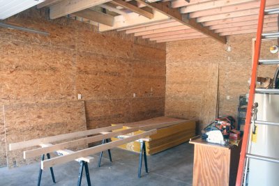 |
April 21, 2007 The picture shows the primer going on, I used a decent (ie: not inexpensive) airless sprayer to apply it. You can also make out the French cleat system I installed on the walls. |
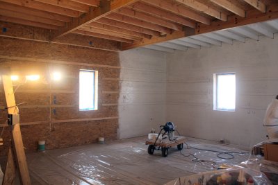 |
Priming and painting took a weekend to do, it's a lot more work than it appears even with spray equipment. Painting brightened up the space considerably. I am pretty pleased with the outcome, the OSB strands and sheet joints can clearly be seen in person but it isn't too objectionable (to me). I almost hate to put lights and other stuff on the ceiling which will ruin this pristine look. The wall color looks kind of gray in pictures but it is actually more of a tope color. The spray equipment wasn't cheap but I figured I could use it elsewhere and it saved an enormous amount of time. |
 |
| For the first time you can see a view of the interior wall separating the tractor bay from the rest of the shop. There is actually another wall to go up on the other side of this wall to complete the separation and make up the stair-well. | |
May 1, 2007 I am now going to re-set an optimistic target of Winter 2007 as the "initial completion" target date. |
 |
|
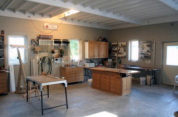
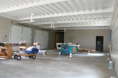
| May 11, 2007 I actually have the shop up and running now. That is not to say it is anywhere near complete. I have had most of the electrical operational for some time now but that does not include lighting. I have been able to place most of my previous shop items generally according to the original plan, this actually happened fairly quickly because nearly all wall mounted items were hung using a French Cleat system and I installed the same system in this shop. Due to different cleat heights I had to adjust a cabinet or three but overall everything went in fine. By the way, it took three whole sheets of plywood to make these; I could have easily used more. I fully intend to make replacements for all theses shop cabinets, these will end up somewhere else. In this picture you can see one of my lighting experiments on the ceiling. I have gone back and forth with numerous calculations regarding what I need versus what the options are and I think I have finally settled upon a design based upon high wattage compact fluorescent lamps (CFL). I have had very good luck with these high output CFL devices and very poor luck with $20 and cheaper 48" T8 and T12 fixtures. Poor reliability of the T8 fixtures became a primary deciding factor in my design decision. Lighting such a large space well is no small task and is going to be expensive As I began to place my previous shop items certain issues started to become self evident. For one, what worked in my small two-car garage is not necessarily going to work well in this larger space. Another thing that is becoming evident is that I didn't put in enough 110v outlets. I actually thought is was more than enough when I was doing it, now it seems somewhat inadequate. |
|
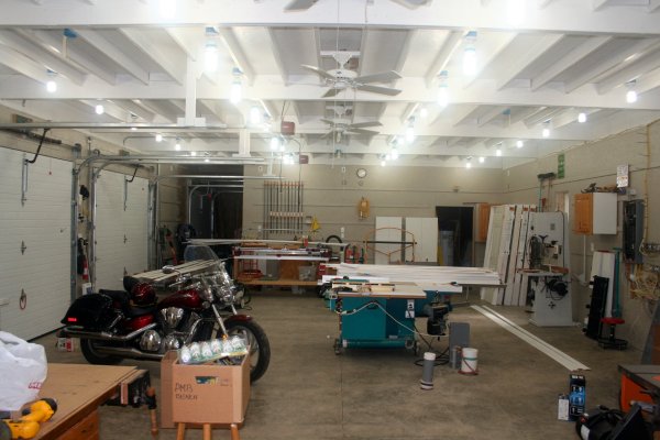
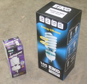
| July 18, 2007 I now have all my main lighting in. It's hard to take a picture of light so the photo above doesn't really convey the actual lighting conditions in the shop. I'm using a mixture of 42 and 105 watt CFL bulbs with a temperature of about 5000k. I did some experiments with different color temperatures and the bulbs with a ~5000k temperature seemed noticeably better. I didn't receive the 105 watt bulbs initially so I filled in the gaps with some cheap 40+ watt bulbs from Menards for a time. The difference between these full spectrum bulbs I bought on line and the Menards bulbs were quite remarkable. The 42w full spectrum bulbs were only a couple of bucks more but they come on instantly and are remarkably whiter and brighter. I have the lights connected to 4 separate circuits (2 per half) so I can turn on only the amount I really need. Overall, there are 48 individual bulbs making up these main lighting circuits. One of the drawbacks of building a large shop is that it requires a lot of infrastructure. That's another way of saying that it costs a lot to even light it up. One can also see the garage door openers and ceiling fans installed. Yet to do are the automatic occupancy light, smoke detectors, and ceiling outlets. |
I'm not aware of anyone else lighting their shops with these CFL bulbs and that caused me some concern when it came time to do the lighting. The ceilings aren't high enough for high-bay lighting fixtures that I was aware of, operating costs and heat is an issue so that ruled out incandescent bulbs; that leaves florescent lighting (fire wasn't considered as a lighting option). As mentioned earlier I had trouble with the moderately priced 4' T8 fixtures. A cost rollup showed that these 4' fixtures were expensive to implement especially given that I experienced a 50% failure rate (note, don't buy fixtures at HD); that made me start looking for alternatives. I found a supplier of full spectrum bulbs on the net and after some more consideration I placed an order. Time will tell if this was a wise move. I used several CFL's in light poles during construction to get an idea of how I would like them and what the failure rate was; I never had a unit go bad to date. The small 42w bulbs are actually among the largest physical size bulbs one typically finds in stores. The large 105w bulbs are so large by comparison they look almost comical. Enclosing these high output bulbs is generally discouraged due to heat issues so all mine are exposed. The ceilings are high enough that it shouldn't be a problem hitting them, time will tell if dust coating is an issue. |
 |
| My calculated cost for
what I installed is about $992, that doesn't include my time to put in 48 fixtures.
The light output calculates to 154 lumens per foot (at the bulb, not the floor).
The cheap T12 fixtures estimated at $840 for 169 lumens/ft but these fixtures hummed and
started poorly thus were deemed unacceptable. Using "better" $20 T8
fixtures estimated at $1344, I had an incredible failure rate with these so they weren't
an option. Going to "even better" high output 4' fixtures and bulbs from
Menards ran the estimated cost up to $1500. This involved fewer fixtures but I
didn't have any experience with these so they entailed more risk. Overall, I'm happy with the lighting levels I have. I did a little research before hand to try and determine what my needs were. I believe that I had about 120 lumens per foot in my old shop (which I thought was okay). A sampling of 12 other shops via the internet yielded a span of 111-202 lumens per foot with 148 being the average. This is a rough calculation but I decided that I wanted something closer to 148 as opposed to the 120 I had earlier. |
|
Aug 11, 2007 Note, picture at right taken 3 months after installation. |
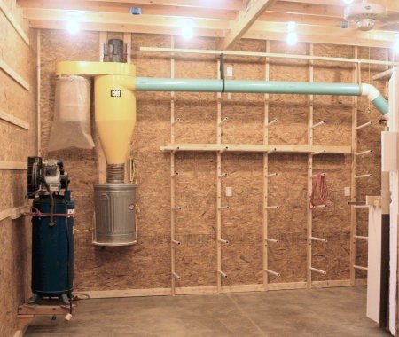 |
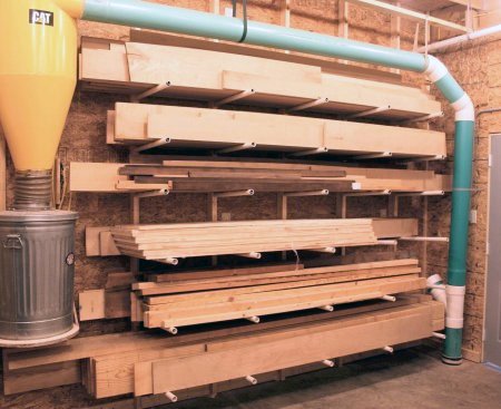
Attachment to the wall is actually very simple via a couple of 2x4's and metal angle brackets. I used my little green monster to lift the fully assembled unit onto the wall and the brackets on the top were simply bolted in. If one had access to a 'Star Trek anti-grav' unit it would be an easy one man operation to install. After that is was a fairly simple matter of wiring it up and connecting the pipe together. As elsewhere, I used 6" PVC pipe to run from the floor connection to the cyclone. The reason I installed the unit up so high was so I could install a tall lumber rack or something under this pipe. My initial test seemed to indicate all was well with the system. The cyclone is located in an area that is as far away as I could get it from the work area and will eventually be enclosed behind a wall and doors when the attic stairway goes in. When I first began designing my DC ductwork I wondered whether my old woodsucker would be able to handle it. My longest run is through over 70 feet of 4 and 6 inch pipe. I was guessing that 2hp was not going to be quite enough thinking that 3hp was probably the minimum if not 5hp. There are two good news items to report here. First, it appears that the thing works well if not extremely well. After a couple of days planing, jointing, sanding, sawing, and routing, it would appear that this unit will work quite well; this is at least a $1200 cost avoidance. The second piece of good news is that the noise reduction I was hoping for is also realized. Having this screaming banshee open inside a two car garage is really not a good thing. By remotely locating the unit the noise to my ear is greatly reduced, it can only get better once I enclose it. I still need to build a few new blast gates and a poor man's remote for the unit. For this I am going to try a $10 wireless remote used to turn 110v outlets on/off. I'll have to make a relay box to switch the 220v needed for this motor. Here is some good reading on PVC and dust collection if you are interested. |
|
Dec 16, 2007 I used a drill jig and a laser level to line up all the hole locations and I am using half-inch black pipe as the support. I'm also sleeving these with PVC pipe so as to any any stain marks that might come from contact with metal pipe on the wood during storage. |
 |
|
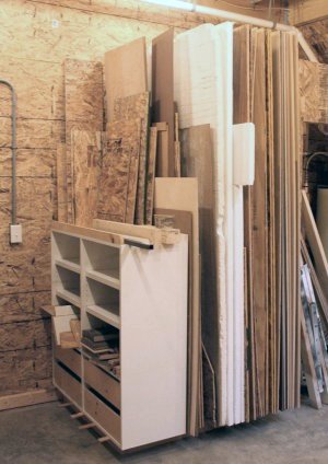
I tested these pipes by putting my
full body weight on a single pipe and it worked fine. The studs are lagged into the
wall purlins as well as being supported by the floor on their ends. Putting this all
together was a little work but probably easier than it appears or sounds. Note how I
raised the DC bin off of the floor to accommodate very long boards underneath. I
really like the storage capacity this method offers, I'll probably use it elsewhere in the
future. I also took care of my plywood storage needs at the same time. I decided to go with vertical storage for this to take advantage of my high ceilings and reduce the footprint on the floor. I built a simple base in a corner area. On one end of this I re-purposed a cabinet for storing small off-cuts to create a well. This well is subdivided by a similar 'pipe in stud' method to keep everything from leaning together. Surprisingly I have found that it is easier to put and pull full sheets of plywood from this rack compared to my old cart storage method. I have further 'shorts' storage under the stairs which can hold plywood up to 5' in length (not shown) |
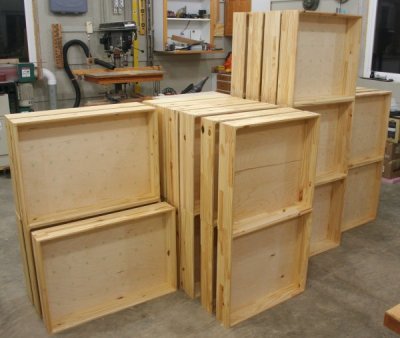
| December 28, 2007 My shop is actually starting to really look like a woodshop now. I stared building a series of cabinets including a large wall mounted clamp rack. All together there will be a series of 4 cabinet sections built all with multiple modules. Included in these are 37 drawers on full extension drawer glides. I had to buy a bunch of material for this of course but I'm also trying to repurpose (use over) existing cabinetry as well as use up some accumulated scrap materials. |
 |
| December 31, 2007 If you haven't been able to deduce this yet, the entire shop has taken me quite a bit longer than I ever anticipated and it still isn't "done" yet. I still have plenty of work to do such as running air lines, window & door trim, machinery changes / upgrades, and a long list of little improvement projects. All in all though I feel that I have met my revised goal of "initial completion" by Winter 2007; I guess that puts me behind my original schedule by about one year. There are a couple of noteworthy pieces of information to pass along at this point. My DC system has worked quite well, I have had no clogs and the noise reduction goals have been achieved. The shop is still noisy but the DC is no longer the single overriding emitter. The problem now is knowing if it is overflowing or not since it is remotely located. I also need to build a remote on/off switch for it. The lighting system has worked well although it doesn't really photograph well in wide shots such as the one above. I have had one 42w bulb failure to date. The heating system also works well. I am finding however that the floor temperature is not as consistent throughout as I thought it would be; the air temperature is quite even though. I really do like the floor heating, there is a definite but hard to describe quality to it compared to air-heating. I think my thermostat occasionally sticks on or off but most of the time the shop temperature varies only about 8 degrees on cold days. One thing I am considering is painting or tiling the concrete floor either in whole or sections thereof. I'm sure it would make a lot of difference on lighting but it's a lot of work to change the floor color. |
|
| January 27, 2008 The current shop project is to build a boat load of drawers for the storage cabinets mentioned earlier. Also built around this time was a large three sided and wall mounted clamp rack (not seen). The 37 drawers are all built of laminated pine planks with the power tool cabinet utilizing box joints and the rest are simple pocket hole joinery. Switching to pocket holes for the bulk of the construction speeded up the process quite a bit. The main goal here is to get the shop in a much more organized state and eliminate the two tables that seem to only accumulate junk as opposed to actually organizing anything. |
 |
 |
| May 1, 2008 Although the configuration of these cabinets is not as per the original layout, this seemed like it would serve better. To the left is a repurposed set of drawer units and a couple of new tall 6 drawer base units. These hold things like extra screws, seldom used tools and other whatnot that I want to have easy access to but don't use on a very regular basis. This cabinet was filled up to about 90% capacity immediately. In the center of the North wall is a three sided clamp rack. Since I mainly use clamps at this end of the shop, I thought this might work out a little better than my original idea for a mobile clamp rack; I thought it would end up always in the way. So far this seems to hold true. This holds all my primary clamps except for several 1/2" pipe and other long clamps. In the right corner nearest the workbench is a 4 unit - 20 drawer base counter. This holds several high use items as well as being the "sacrificial horizontal surface" where I can set stuff down without rendering the main work bench unusable. This was filled to about 60% capacity at the start. Between the walk door and overhead door #1 is a peninsula style drawer and door cabinet. The top has door openings on either side, this back side has a cleat system for holding jigs and stuff. The front near the walk door (not shown) is a 5 bay drawer unit housing all my commonly used power tools. This was filled to about 95% capacity immediately - probably should have made it bigger. None of these new storage units have their false drawer fronts made yet. |
| May 9, 2008 No significant shop progress to note but an important item to mention. It seems my old shop had caught the attention of Wood Magazine for their annual "America's Best Home Workshops" issue. This is one of their special interest publications (meaning subscribers don't get them). When I explained that I no longer had that shop and had built a new one they asked for current pictures of that and when I thought it might be photo-ready. Evidently they liked what they saw and we agreed to a shoot date around mid-June (2008). By agreeing to this I basically put myself behind the eight ball here as I had several tasks to complete in order to get the shop in shape where I would not be embarrassed. Among the numerous small items that had to get done, I also had these major tasks to complete in addition to just cleaning the shop up real nice:
To get all the stuff done I made a list, prioritized it, and went to work - as it turned out, it was a LOT of work. |
June 6, 2008 |
 |
 |
| June 16, 2008 In addition to the items listed above for the Wood magazine article, I also added the purchase of three new machines to the task list (which I had planned to do anyway), might as well do it now. This also meant that at least one of these would need a base of some sort too as it came without one. A new 15" wide belt sander to replace the drum sander, a small metal working mill, and an 8" jointer. The jointer base arrived damaged so it was several days before I could get that up and running, everything else was in good order and didn't take long to setup. |
 |
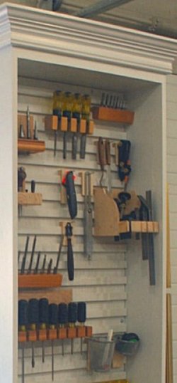 |
Besides the new machine delivery, I
also got several other small jobs accomplished by this time. One of these is a
French cleat tool holder system. I had originally planned on using a pegboard system
on the exposed end of the power tool cabinet but I though the cleat system would work out
a little better. There is some labor in building a multiple cleat board like the one
shown here but it does have some small advantages For one, the custom holders are
slightly easier to build. The main advantage though is that the custom holders are
easier to move around or transfer to other boards. With a peg-board system, I found
I often had to unload the holder completely before it could be moved. I'm pretty happy with the system overall but due to the labor involved in making the cleat board, this isn't worthwhile for everyone or every situation. For those interested, the "board" is common BC 1/4" plywood, the cleats are 1/2" pine or mdf cut at a 45 degree angle glued and stapled to the plywood. They are about 1" wide with a 1 1/8" gap between boards. This seemed like the minimum width of cleat for the strength required. I suppose one could get away with using 1/4" stock for these, I might try that sometime. The holders vary quite a bit in design. The most simple is just a strip of 1/4" ply with a cleat glued to the back and lopped off to a suitable width with a finish nail driven in for a peg. Sounds like a lot of work compared to a simple peg-board hook but it isn't. Other simple ones are holes bored in a chunk or wood with a cleat glued on while others like the square holder required a bit more thought. If you are wondering, there are no plans or drawings available for these. |
| June 21, 2008 I finally got around to plumbing up my big air compressor - this is something I should have gotten to long ago but I was procrastinating. Most of the reason for that is I hadn't made up my mind as what to use for pipe. Ideally this would have been done before I sheathed the walls even but running the lines inside like that does not provide much flexibility for change at a later date. I debated about using copper, PVC (I've used it in the past, it's generally considered a BIG no-no though), and PEX. |
 |
| There are other materials
that can be used as well like steel pipe, I think that's harder to work with and rusts.
There is also a modular aluminum pipe system but it's pretty expensive. One
could also just use air hose, I thought about that too since it would be fast and low
risk. At the time, there wasn't a whole lot of info on the web concerning the use of PEX for compressed gasses. Nobody comes right out and says it cannot be used but they don't recommend it either. There is a kind of PEX specifically made for this but it's hard to find thus not a real option. Basically what I'm saying here is that there is some risk in using PEX. Unlike PVC or CPVC, the failure mode of PEX isn't catastrophic; it splits instead of blowing up. One good thing about having to meet a deadline is it forces you to get off the fence and "git-r-done"; I chose PEX. I had originally thought to use the more expensive pipe with an aluminum lining but then I got to thinking that I'm not building a rocket ship here and "super pipe" would be overkill and extra cost for no real benefit. I used ThermaPex pipe along with a HydroPex clamps and a ratcheting clamp (crimp) tool. One minor reason for using this pipe is the color, it blends in to the wall pretty good. I may eventually paint over the piping anyway as they say UV is bad for the PEX pipe. I selected the particular connection clamps because of the tool. With a ratcheting tool there was no need to use a go-no-go gauge and it's easier to use than a brute force crimp tool. As for the design, I used all PEX type fittings everywhere meaning I didn't mix it with any other plumbing type. What this boils down to is that if I needed two lines in the same general area, I ran two branches. I used a 3/4" main line run along the bottom of the wall wherever possible and 1/2" branches to several outlets. I initially bought all but the crimp tool on-line but redesigned the layout prior to actual installation and ended up buying probably half the fittings at Menards. In addition to the compressed air, I'm also running water to exterior hydrants with 3/4" PEX (bottom pipe run in picture above). Typically air systems are run overhead with branch drops. When done correctly this helps (but doesn't totally eliminate) to keep moisture out of the branch lines. I didn't want the pipe taking up that much visual space and it somewhat interferes with cabinet etc placement on the wall so I decided to run the pipe low. To attach the system to the wall I used metal strap clamps on the 3/4" main and clip-on clamps from Menards for the branch lines. These clamps from Menards where MUCH better than the nail on clamps I got on-line and I highly recommend these over any nail-on device. Not that I am any expert but I've done a fair amount of plumbing before and I was pleasantly surprised at the speed of installing this PEX pipe. I'm happy with the install and would do it again without hesitation. Time will tell how it holds up and I will keep this section updated if there is any news to report on that. |
|
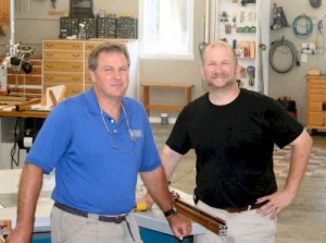
| July 17, 2008 The day of the photo shoot, I've included a picture of Marlen Kemmet from Wood Magazine and the photographer Jeff McSweeney as "proof" of this. I had about two months to get ready for this and it was an excellent motivator for getting a host of shop projects completed that otherwise I probably would have taken all year to do. I'm glad this day finally came and went, now I can slack off again, man that was a lot of work! I'll probably write a small article on this experience. The shop really isn't "done" yet, it will never be "done"; it's a lot closer to that though. |
 |
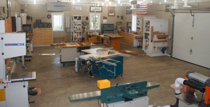 |
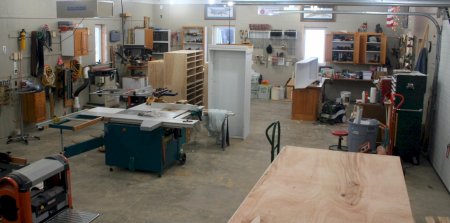
| Above we have a nice
pretty view of the shop with everything in it's proper place and all cleaned up. It
doesn't look like this very often. I washed the floor down with a garden hose, when
the floor is actually clean it's somewhat dark like this. I'm thinking of painting
the floor but haven't decided yet. Notice the plethora of storage units, hand tools, jigs, several machines, wall art and lots of other stuff. This is what most of us would think of when we think of a big woodworking shop.
|
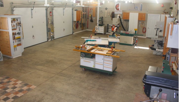 |
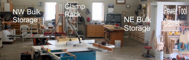
| Now here is a Southern
view of the shop; contrast this with the photo above. Notice that in this view there is a lot of boring empty floor space (this gave the photographer composition problems). Compared to the view above this is certainly less entertaining but I would submit to you that THIS view represents the original design goal of the shop more clearly than any other. One of the primary goals of this shop is to provide enough "free" space for two major projects at the same time - what you see here is that requirement fulfilled. For the record, my previous two car garage shop had about 70 square feet of free space, that's a 7x10 spot; obviously I have a lot more than that now. It doesn't take long for a woodworker to run out space in a shop. Organization is a tool that helps but if you plain don't have the real estate, you just don't have it and a shop without free space to work in is very inefficient. While most of us are tool nuts to one degree or another, woodworking shops aren't totally about the tools in them; it's really the ability to do some type of activity in them and free space is really the thing that allows that to happen efficiently. |
 |
| While I'm at it here I'm including a picture of the view outside the North windows of the shop. The shop sits on the Eastern bluff overlooking the Illinois river valley. Down below is a large farm planted in corn, across the river is the little town of Chillicothe. |
Return to the New Woodworking Shop Index
 |
 |
 |
 |
 |
 |
 |