|
|
|
BT3100 Sliding Miter Table Alignment
 |
 |
 |
 |
 |
 |
 |
| Note: | Like most sliding tables, the SMT unnecessarily couples more than one alignment feature together. This makes the process very interdependent and tedious. The alignment theory is very similar to the alignment of the rip fence. | |
| Goal: | The direction of travel of the SMT should be set as close to parallel to the blade as possible. Note, this alignment is also true of miter gauges. It should also be even with or slightly above the plane of the saw table and at the same angle. | |
| Tolerance: | The travel
should be within +/- 0.004" of parallel (over the measured blade distance). The height should be -0.0" to +0.01" relative to the main table. Its height should be even (not at an angle) with the main table by +/- 0.02" at the far left edge. |
|
| Error Effect: | Even if the
travel is not parallel, one can still achieve a square cut; the cut will only be square on
the face though. If the travel is out of tolerance by a small amount, one end of the cross
cut will have slightly fewer saw marks and the other will have slightly more. The cut will
be a very slight cove, so slight that it will be difficult to observe (on �" thick
stock). If the travel is out of tolerance a little more, there will be excessive saw marks
and probably more chip-out on the cut. If the table is lower than the main table stock may catch on the main table as it is pushed towards it, this is an opportunity for injury. If the table is higher than the main table, there is a chance for an induced blade angle cut or more chip-out at the bottom of the cut. These conditions will also apply if the table is angled (higher or lower at the edge opposite the blade). |
|
| Process: | Free-play in
the table should be taken care of first. The SMT uses small plastic guide tabs as table
glides. Unfortunately, the design of these tabs tie SMT table angle (relative to its base)
and table freeplay / friction together. It is more important to control freeplay
than the table angle markings in this case. To adjust the freeplay, loosen the
lock nut on the top of the table and adjust the cam so there is as little as possible side
play in the table. If the tabs are too tight the table won't slide at all. The tabs
are also wear items which may cause a loss of alignment after a period of use. Unplug the saw for safety. The SMT on the BT3100 is clamped on both ends to the rip fence rails. There are aluminum blocks with two setscrews that make up part of each clamp. The setscrews are an aide to position the blocks relative to the rip fence rails, in theory, these control angle alignment. The SMT is set onto the rip fence rails; with shims one can control table height and angle. Table angle is also a function of rip fence rail alignment. Table height and angle alignment can be checked very easily with a straight edge and feeler gauges. Simply compare the SMT table to the main table and adjust accordingly if required. |
|
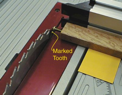
| A jig will be used to
measure direction of travel alignment. The jig is nothing more than a length of wood with
a screw threaded into its end. The measurement technique is the same as used for rip fence alignment.
There are more sophisticated techniques that can be used but this will suffice. Install the jig onto the SMT by clamping it to the table or the crosscut fence. Using the marked blade tooth, move the SMT to allow the screw head to be close to the marked blade tooth and then adjust the screw so that it barely makes contact with the tooth, this is the initial reference or "zero" point. |
 |
|
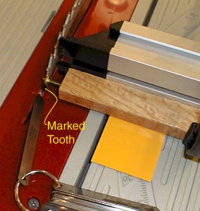
| Now rotate the blade and
move the SMT to place the jig adjacent to the same marked tooth. If the travel is very
close to parallel, the contact between the screw and tooth will make the same sound. If
this is true, the travel is parallel. If there is a gap, the travel is angled away from
the blade. To measure the gap, use a set of feeler gauges. The one that fits between the
tooth and the screw is the amount of misalignment (over the measured distance). If the
screw head projects past the tooth, the SMT should be angled to travel away from the
blade. If a feeler gauge greater than 0.004" fits between the gap, one should attempt to align the travel better. If the travel cannot be set parallel, it would be slightly better to have the error with the travel angled away from the blade on the side it is normally used. This is sometime referred to as a "free cut". |
 |
|
To actually
make an alignment adjustment:
Ideally, the SMT will hold it's alignments as long as the BT3100 rip fence rails have not been moved. If they are moved, alignment should be re-checked. Ideally the SMT could be repositioned on the rip fence rails and it would still hold the parallel alignment within some very small tolerance. |
||
 |
 |
 |
 |
 |
 |
 |